• Welcome to the new and improved Building Code Forum. We appreciate you being here and hope that you are getting the information that you need concerning all codes of the building trades. This is a free forum to the public due to the generosity of the Sawhorses, Corporate Supporters and Supporters who have upgraded their accounts. If you would like to have improved access to the forum please upgrade to Sawhorse by first logging in then clicking here: Upgrades

Natural Gas Piping Pressure Test

Michael.L

Registered User
Joined
May 10, 2018
Messages
206
Location
Boulder County, CO
I'm trying to understand the procedure involved in performing a pressure test of natural gas piping.

Reading the manual for one of the gas appliances (an oven) for our shop, it states:

The oven and its individual shutoff valve must be disconnected from the gas supply piping system during any pressure testing of that system at test pressures in excess of 1/2 psig (13.85” W.C., 3.45 kPa).

The oven must be isolated from the gas supply piping system by closing its individual manual shutoff valve during any pressure testing of the gas piping system at test pressures equal or less than 1/2 psig (13.85” W.C., 3.45 kPa).
The way I read that, the individual shutoff valve is the gas valve on the piping just before the piping outlet to the appliance (e.g., where the flexible gas connector for the appliance connects). Since typical commissioning pressure tests are performed at over 3 psi, does that means all shutoff valves must be removed from the piping? Or is this requirement only for those small flare-end shutoff valves that are only rated to 5psi?

What about the FIP x FIP gas ball valves that are rated over 150psi? My piping design uses these types of valves followed by a tee and a sediment trap; the tee is where the appliance's flexible gas connector is connected to the gas supply piping. If these valves had to be removed, there would be no way to test the integrity of the sediment trap.

I'm not even sure why those small flare-end shutoff valves exist since they preclude the use of a sediment trap (unless you install two shutoff valves at each appliance connection.
 
Not a plumber or plumbing inspector.

The tests I have seen, including in my house,

The valve is left in place, just closed.

I think there is a difference between manufacture instructions and code requirements.
 
Not sure if this applies, but looks like it


1213.1.4 Piping System
A piping system shall be tested as a complete unit or in sections. Under no circumstances shall a valve in a line be used as a bulkhead between gas in one section of the piping system and test medium in an adjacent section, unless two valves are installed in series with a valved "telltale" located between these valves.

A valve shall not be subjected to the test pressure unless it is determined that the valve, including the valve-closing mechanism, is designed to safely withstand the pressure. [NFPA 54:8.1.1.5]

https://up.codes/s/pressure-testing-and-inspection
 
NFPA 54 does not allow testing against a live valve with gas on the other side, and you are correct on the damage to the valve that may not be rated for test pressure.....Plus if the equipment was connected and the valve was accidentally opened you might blow out the gas Software and create a dangerous condition on startup....
 
NFPA 54 does not allow testing against a live valve with gas on the other side, and you are correct on the damage to the valve that may not be rated for test pressure.....Plus if the equipment was connected and the valve was accidentally opened you might blow out the gas Software and create a dangerous condition on startup....

So say at a house, the plumber is supposed to remove all the valves, and cap the line, prior to the test?

The valves are not designed for 15 or 20 psi pressure on them?
 
The MFR restrictions seem to mirror the code. (2018IFGC) We run into this when the utility turns the gas off or locks out the meter due to a leak and requires the inspection department to retest the system. Since test pressures used are far in excess of the rated operating pressure of the appliance the code requires disconnection.

406.3.3 Appliance and equipment disconnection. Where the piping system is connected to appliances
or equipment designed for operating pressures of less than the test pressure, such appliances or
equipment shall be isolated from the piping system by disconnecting them and capping the outlet(s).


406.3.4 Valve isolation. Where the piping system is connected to appliances or equipment designed
for operating pressures equal to or greater than the test pressure, such appliances or equipment
shall be isolated from the piping system by closing the individual appliance or equipment
shutoff valve(s).
 
the code seems to require a cap or plug at the connection points, leave valves in place, nipple with cap or plug. seem to be a belt and suspender approach to possible damage to the appliances
 
For example....


Gas Ball Valve - Female x Female, Lever Handle

GB1A
  • Valve pressure rating 600 psi/41.4 bar non-shock cold working pressure, RPTFE seat, FIP x FIP end connections, Not for water service
  • 1/2 psi for indoor appliance connections per ANSI Z21.15 and CSA 9.1, 5 psi for indoor shutoff per CGA 91-002 and ASME B16.44
  • Size range 3/8" to 1"
This is the problem I'm talking about. I understand that they do not want this valve installed on a high-pressure gas line, but why wouldn't you be allowed to test this valve at say, 10 psi when it's capable of withstanding 600 psi? Seems nuts.

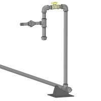
This is my proposed gas connection to a rooftop makeup air unit. How do I test all this piping if I have to remove the valve?

Gas Connection.jpg
 
Last edited:
Plus if the equipment was connected and the valve was accidentally opened you might blow out the gas [regulator] and create a dangerous condition on startup....
Just to be clear, my thoughts on testing the piping would be to remove all the connections to the gas appliances and cap the gas supply piping outlets.
 
You can NEVER pressure test the final connection (or 2)......Maybe a soap test or something like that, up to the inspector as to what they are comfortable with....
 
You can NEVER pressure test the final connection (or 2)......Maybe a soap test or something like that, up to the inspector as to what they are comfortable with....
I'm not worried about the one or two final connections to the equipment. But if I have to remove the valve in the example piping I posted above, that would take 12 joints out of the test.
 
Leave the valve open and cap the ends of the pipe. You are not pressure testing against the valve and seat.
This is your answer. But a plank pan in the union and do the pressure test with the valve in the open position.

If the inspector desires, the union, nipple, and connector can be soap tested.
 
FYI>>>>

WARNING: NIBCO does not recommend applying pipe compound on threaded joints, and under no circumstance should both PTFE tape and pipe compound be applied to any threaded joint.
 
Leave the valve open and cap the ends of the pipe. You are not pressure testing against the valve and seat.
It was my intention to leave the valves open and cap the pipe openings. It wouldn't be possible to test the sediment trap if the valve were closed. My concern was not so much the valve seat (which should be able to withstand considerable pressure, but rather the valve stem sealing glands.
 
WARNING: NIBCO does not recommend applying pipe compound on threaded joints, and under no circumstance should both PTFE tape and pipe compound be applied to any threaded joint.
I'm surprised that a reputable company like Nibco would write such a statement; I have to researrch this more to see what types of valves and services this statement applies to.

Historically, pipe dope is much more common for sealing gas piping joints because, if not properly applied (or carefully and fully cleaned off when disassembling/reassembling a joint), teflon tape can shred and foul downstream gas valves and regulators. Furthermore, teflon tape is not a thread sealant per se (see below).

For applications like this, I prefer the use of Loctite 565 PST (which is a controlled-strength anaerobic thread sealant with PTFE).

Here is a great overview of the three main types of thread sealant from an article published by Plant Engineering:

Types of sealants

There are three basic types of pipe sealants in use today: teflon tape, pipe dope, and anaerobic resin compounds. The experience of the technician and availability of the product dictate which one is used. Each type has properties to recommend its use.

Teflon tape

The purpose of this white, nonsticking tape is to serve as a lubricant when threaded parts of a piping system are being assembled. The inherent slipperiness of the material makes assembly easier.

Strictly speaking, Teflon tape is not a thread sealant (Fig. 1). The tape may have the effect of clogging the thread path, but it does not actually adhere to surfaces as a true sealant should. During installation, the tape must be carefully wrapped in the direction of the threads or it unravels and tears.

Advantages . Teflon tape can be applied quickly with no mess. It supplies sufficient lubrication to enable pipe system components to be easily assembled without damage to threads. The product is easy to carry and store, and has an indefinite shelf life.

Disadvantages . Teflon tape does not adhere to thread flanks, and does not provide a secure seal. Because the tape is thin and fragile, it is prone to tearing when pipes are being assembled and tightened. Bits of torn tape can migrate into a fluid system, clogging valves, screens, and filters. Teflon tape may be dislodged during pipe adjustments, allowing leak paths to form.

Recommended uses . Widely used in plumbing, this material is adequate for assembling standard water pipes and fittings. Teflon tape offers no resistance to vibration and should be avoided in high-pressure systems.

Pipe dope

Pipe dope has been used in industrial applications for decades. The material relies on a solvent carrier and hardens when the solvent evaporates. The resulting seal adheres to all plastic and metal pipes and effectively blocks leak paths.

Because it contains solvents, pipe dope has a tendency to shrink over time as the solvent dissipates. This condition creates the potential for the dope to pull away from the thread walls or crack, allowing leaks to develop. Pipe dope is usually applied to threaded components with a brush or spatula.

Advantages . Pipe dopes are inexpensive and relatively easy to use. Their chemical composition is compatible with all pipe materials, including plastic. Pipe dopes harden quickly and produce a moderate to strong seal.

Disadvantages . Solvent-based pipe dopes can lose their effectiveness as the result of heat aging. When the seal shrinks and cracks, leaks can develop. This possibility is especially true with systems that are subjected to significant vibration. Pipe dopes may lack sufficient resistance to solvents.

Recommended uses. Solvent-based pipe dopes provide an adequate seal in applications where high temperatures and pressures are not expected. Pipe dopes offer minimal resistance against vibration. They are acceptable when the installation of a piping system does not require adjustment of components more than a few minutes after assembly.

Anaerobic resin compounds

Anaerobic resin compounds use a different cure chemistry than solvent-based pipe dopes and do not contain solvents. The cure begins when the sealant is confined within the threads of the metal pipe connection and air is excluded.

Without solvent content, the cured material does not shrink or crack, and maintains its sealing properties even after heat aging. Because of their chemistry, anaerobic resin compounds exhibit excellent temperature and solvent resistance.

Advantages . Anaerobic compounds fill the voids between pipe threads, creating a seal (Fig. 2). The compounds cure slowly, providing additional time to make adjustments to pipe system components without damaging the seal. Once cured, the compounds form a strong seal that resists the effects of temperature, pressure, solvents, and vibration.

While some sealants produce bonds that make disassembly difficult, joints sealed with anaerobic resins can be taken apart with standard hand tools. Many anaerobic thread sealants contain Teflon or similar lubricants which aid assembly and reduce the potential for damage to pipe system components.

Disadvantages. Because of their chemical composition, compatibility of anaerobic resin compounds with plastic pipe and fittings should be verified before use. Although these compounds cure sufficiently for many immediate uses, a 24-hr period should be observed before activating high-pressure systems or allowing significant shock or vibration. Anaerobic resins can be difficult to remove from clothing or gloves.

Recommended uses. This class of sealants provides the strongest, longest-lasting seal presently available. They are recommended for temperatures up to 300 F, pressures up to 10,000 psi, and where vibration will be encountered. These sealants are the choice when installers must make minor adjustments to a piping system.​
 
So say at a house, the plumber is supposed to remove all the valves, and cap the line, prior to the test?

The valves are not designed for 15 or 20 psi pressure on them?

This is always a point of contention....one I have to try and explain nearly every time. I too have questioned the validity of the idea that the valve can't handle the pressure and I have determined that the reason for the capping isn't because the valve can't handle the pressure. It is because, if for some reason, the valve got opened while under the higher pressure the appliance could be damaged, maybe without anybody knowing it (which could have pretty bad consequences beyond the damaged appliance). Of course, this is just my rationale, I could be wrong.
 
Top