• Welcome to the new and improved Building Code Forum. We appreciate you being here and hope that you are getting the information that you need concerning all codes of the building trades. This is a free forum to the public due to the generosity of the Sawhorses, Corporate Supporters and Supporters who have upgraded their accounts. If you would like to have improved access to the forum please upgrade to Sawhorse by first logging in then clicking here: Upgrades

Concrete stair railing can not meet 4.5" handrail requirement?

gnarkill283

Registered User
Joined
Nov 15, 2017
Messages
107
Location
New York
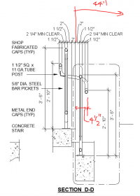
Can someone please explain to me why stairs are only allowed to have 4.5" of handrail projection when most concrete switchback stairs have the inner railing of the handrail cast into the stair requiring at least 2" of concrete surrounding the post. This mean the entire assembly from edge of stair to edge of handrail can only be a minimum of 7.25": you have 2" of concrete then 1.5" min guardrail diameter then 2.25" min clearance between guardrail and handrail then 1.5" min handrail diameter = 7.25". The only solution we are pursuing is to widen the stair beyond the required capacity so that the combined projection of handrails is less than 9" (hopefully this will be allowed as the wall side handrail projects min. 3.75"(1.5+2.25") and the extra .75" can be added to the other side). So if you have the minimum required stair capacity width of 44", the actual stair width will have to be 46" (3.75+7.25 = 11" - 9" combined projection = 2" added width to stair.
 
Can someone please explain to me why stairs are only allowed to have 4.5" of handrail projection when most concrete switchback stairs have the inner railing of the handrail cast into the stair requiring at least 2" of concrete surrounding the post. This mean the entire assembly from edge of stair to edge of handrail can only be a minimum of 7.25": you have 2" of concrete then 1.5" min guardrail diameter then 2.25" min clearance between guardrail and handrail then 1.5" min handrail diameter = 7.25". The only solution we are pursuing is to widen the stair beyond the required capacity so that the combined projection of handrails is less than 9" (hopefully this will be allowed as the wall side handrail projects min. 3.75"(1.5+2.25") and the extra .75" can be added to the other side). So if you have the minimum required stair capacity width of 44", the actual stair width will have to be 46" (3.75+7.25 = 11" - 9" combined projection = 2" added width to stair.
My suggestion is to add returns to your math simpler to read

But the code does not care about the space between guards, it interps it as a zero thickness, remember they produce a minimum and the 4.5 is a max inward projection from wall or guard surface.

The 2.25" is a NFPA and OSHA requirement not an IBC requirement also, ADA/ABA and IBC only require 1.5", thus you gain a reduction of 1.5" combined.

The funny thing about the code it does not tell you how to build the stair, it only tells you, that you need a minimum of 44" between the walls/guards above the handrails to 80", and then the handrails are allowed to project inward 4.5" from each side, thus your 9".

The problem is designers, architects and engineers don't look at the total requirement, just the 44"

When I teach this subject to designers about designing stair flights, I start with the required 44" and then tell them to add the guard design or walls,

now from this point figure out the additional stair width needed to hold the guard in place for the type of stair you are building.

Now design the stair tower to fit the requirements.

ITs not in the inward projection fault of the handrails, its the designers fault for not understanding the correct size and areas needed to install what they want.

Yes, your math is correct if installing concrete stairs in that manner with a 2" offset needed.

Do a different stair construction design or provide the correct space needed for the tower, but don't call out the required offset's as the issue.

However, the 4.5" is 1/2" larger that all the other protruding objects limits. Which max out at 4"

You can also gain room with 1.25" handrails rather than 1.5"
 
Last edited:
I don't fault the code. I just doubt many architects are aware of this (my boss wasn't when he sketched out the stair originally) and don't recall this ever coming up with plan examiners on past projects were this wasn't taken into account. I also worry the plan examiner won't understand why the stair is wider than its life safety capacity. So if I understand you correctly, the guardrail is technically a wall and needs to be clear of the minimum 44" stair requirement. Well then my above solution doesn't work as the outside edge of the guardrail is just within the 44". We have no options though at this point so we will see how the city interprets it. Btw this is a fire stair so it has to be 2.25" clear. Reducing the handrail to 1.25 will only get us another half a inch.
 
Why can’t the handrail be continuous, why does the switchback have to be so much wider?
 
1638394829861.png

I think the O.P is saying that the code only allows 4.5" of encroachment into a stair width, but the constructability works out like this:

2" concrete coverage outside of post for guardrail
1.5" diameter post for guardrail (a commonly used size)
min. 1.5" clearance between guardrail and a handrail (ADAS 505.5)
min. 1.25" dia. handrail
TOTAL PROJECTION from outside edge of concrete stair = 6.25", but only 4.5" is allowed.

In the image the OP provided, it added up to 7.25".

If there is not room to make a wider stair, then an alternative solution might be to cast in some metal plates on the side of the stair runs, where the OP is showing a 2" gap between runs. A guardrail "cage" could be welded to these side plates, in between both runs and serving both runs, and the handrails welded to this central guardrail. this would keep it within 4.5" max. projection.
 
Is that concrete coverage confirmed?

Looks like CIP stairs; can the 2" gap in the center go away?

I've heard of situations where the cast in place rail post bases were VE'd to cored railings (3" core needing 4" of edge distance [possibly larger], so a post that was designed to be 2" from the edge was actually ~4.75" away) and the final/ actually constructed clear width was undersized. Similarly, for screw down bases the screws can be outside the footprint of the post and I would expect to see a 2" or 3" edge distance to achieve rail loads. Because of this, and because of TBZ's notes; this is why I design my clear width to the guards not to the stair edge (unless I'm doing a straight run).
 
View attachment 8401

I think the O.P is saying that the code only allows 4.5" of encroachment into a stair width, but the constructability works out like this:

2" concrete coverage outside of post for guardrail
1.5" diameter post for guardrail (a commonly used size)
min. 1.5" clearance between guardrail and a handrail (ADAS 505.5)
min. 1.25" dia. handrail
TOTAL PROJECTION from outside edge of concrete stair = 6.25", but only 4.5" is allowed.

In the image the OP provided, it added up to 7.25".

If there is not room to make a wider stair, then an alternative solution might be to cast in some metal plates on the side of the stair runs, where the OP is showing a 2" gap between runs. A guardrail "cage" could be welded to these side plates, in between both runs and serving both runs, and the handrails welded to this central guardrail. this would keep it within 4.5" max. projection.
Yikes,

Here is my question if you have 2 walls on each side of the stair flight how much distance needs to be between them?

44" or 40.5""

The 4.5" from outside the guard is not how I interp the requirement, the protruding objects needs to be from the inside of guard, as the guard is the most inward portion when its above the handrail height, hence no difference than another wall on that side.

Based on the OP diagram, I interp that the 44" is needed between the inside of guard to the wall, if the stair flight per calcs needs to be 44" wide between walls and not allowed the 36 reduction.

In comes the question Is not the guard system considered a wall surface on that side when it reduces the required width?

What if that was a 42" high wall instead of an open guard?

The protruding objects handrail is offset inward from wall(s) and or guard(s) depending on what is there.

The OP is in a jurisdiction that requires NFPA 101 be followed, hence the 2.25" between handrail and wall/guard, not 1.5".

The OP's 7.25 is based on the following
  • 2" from the openside edge to the outside vertical face of the guard
  • 1.5" for the width of the guard
  • 2.25" for the NFPA 101 Min. Clearance to handrail from inside vertical face of the guard
  • 1.5" for the Handrail Profile width
    • This adds up to 7.25"
The OP then took the 2.25" clearance and 1.5" handrail profile for the opposite side where the wall is and added them together for 3.75"

Now when you those 2 numbers together, 7.25" + 3.75" = 11" reduction, which I am trying to figure out what it has to do with anything because protruding objects are wall dependent not averaged, you can't use the 3/4" from one side to extend in 3/4" more than 4.5" on the other side; the 4.5" is a max from wall/face of guard above handrail height.

However, based on a 3.5" reduction from outside edge of the open side of the stair tread, the width of the tread from wall would need to be 47.5" to be clear width from the guards inside face to wall if staying all vertical, and then each side allows' the handrail reduction of 4.5", when mounting the guard on top the treads inward as drawn in the OP.

I have worked on projects and converted them to comply with 44" widths and 2" clears with a design shown here for concept below.

The space below the handrails becomes void, unless a local Jurisdiction amends the IBC to require the area below the handrails also meet min. width.

Not sure why they do that, as a human body shape has the arms hanging on the sides and as thus once gripping the handrails the natural flow will not have the feet or legs going under the handrail area.
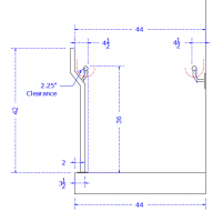
44 width guard hr.PNG
This design complies with a 44" width with a top mounted 3.5" inward bottom mounting, or 2.75" centerline.
 
The space below the handrails becomes void, unless a local Jurisdiction amends the IBC to require the area below the handrails also meet min. width.

Not sure why they do that, as a human body shape has the arms hanging on the sides and as thus once gripping the handrails the natural flow will not have the feet or legs going under the handrail area.

View attachment 8402
This design complies with a 44" width with a top mounted 3.5" inward bottom mounting, or 2.75" centerline.

tbz, the key requirements for max. 4.5" projections are found in IBC 1014.8:
"Projections into the required width at stairs shall not exceed 4 1/2" at or below the handrail height. Projections into the required width shall not be limited above the minimum headroom height required in section 1011.3."
So in theory, a straightforward reading of this allow walls BELOW the stair handrails to project inward 4.5" on either side, making the tread width on a 44" wide MOE only 35" (for handrails at ramps, the minimum is 36").

Your detail generally appears to work and is an elegant solution. One nitpick: you show the clearance below the handrail (red dotted line) as radiused. I don't think ADAS 505.6 recognizes a radius for its 1.5" clearance, so you may want to double-check that with a second "ADA" dotted line, especially if there are 4" o/c horizontal guardrail members going between the posts:
1638476690069.png
1638476603953.png
 
Last edited:
tbz, the key requirements for max. 4.5" projections are found in IBC 1014.8:
"Projections into the required width at stairs shall not exceed 4 1/2" at or below the handrail height. Projections into the required width shall not be limited above the minimum headroom height required in section 1011.3."
So in theory, a straightforward reading of this allow walls BELOW the stair handrails to project inward 4.5" on either side, making the tread width on a 44" wide MOE only 35" (for handrails at ramps, the minimum is 36").

Your detail generally appears to work and is an elegant solution. One nitpick: you show the clearance below the handrail (red dotted line) as radiused. I don't think ADAS 505.6 recognizes a radius for its 1.5" clearance, so you may want to double-check that with a second "ADA" dotted line, especially if there are 4" o/c horizontal guardrail members going between the posts:
View attachment 8404
View attachment 8403
Yikes,

I get all the sections and protruding objects, but what you are forgetting is that the handrail clearance beneath the handrail is allowed to be reduced .125" per every 1/2" of perimeter the handrail is over 4".

Thus, with a 1.5" diameter handrail you have a permitter of 4.7" aprx, thus you only need to be 1.375" down beneath the handrail, not 1.5", and when you do a 2.25" offset from the edge of a 1.5" diameter handrail, hence the radius, it passes the line 1.5" horizontal over and 1.375" down from bottom 1/10,000 over the required square off.

Something only those of us in the detailing world that draw it everyday, know, its a habit to create clearance area when I draw.

If I was doing the 2.25" full clear you are correct the offset is further down for 2.25 over and 1.375" down, I was just trying to point out were the 44" is measured between above the handrails, not the actual tread edge.

and I was showing the full inward projection of 4.5" with the vertical mark out below.

was not really trying to show full clear.

The second point I was mentioning, is that there are a number of local AHJ that modify the 44" width to also include the area under the required clearance beneath the handrail, which was my point that, per model code in the IBC, AnSI a117.1 and ADA/ABA the area under the handrail is allowed to project inward below handrails 4.5", but most jurisdictions will hold it to the actual distance a handrail face lands.
 
Last edited:
Top