• Welcome to The Building Code Forum

    Your premier resource for building code knowledge.

    This forum remains free to the public thanks to the generous support of our Sawhorse Members and Corporate Sponsors. Their contributions help keep this community thriving and accessible.

    Want enhanced access to expert discussions and exclusive features? Learn more about the benefits here.

    Ready to upgrade? Log in and upgrade now.

Number of Jack Studs - gable wall

Darren Emery

REGISTERED
Joined
Oct 20, 2009
Messages
510
Location
Manhattan, Ks
Table 502.5(1) will tell us how many jack studs required on headers for bearing walls, where roof load is a factor.

How do you handle a gable end wall, where the load is not a standard roof load (in my particular case, a perpendicular ridge beam bears on this wall.) How do you decide how many jack studs required?

Any thoughts?
 
I assume that header span charts including jack stud requirements account for point loads such as the one described, and would be comfortable substituting the length of the ridge beam for building width in this example.

Great question Darren. I am curious to see what the DP's have to offer on this one.
 
That's how I've handled this one - without another chart to go to - I've utilized 502.5(1) with the thought that the beam load replaces/accounts for the roof load. It seemed like I was on pretty solid ground requiring complance with the chart, or PE review.

The challenge really comes up when there is no point load, and a simple gable wall. Seems like a stretch to apply this chart, but what else can we do. I get tired of throwing the PE review card on the table, for everything not covered specifically in the code...
 
I'm not sure I understand. Are you asking what size the column under the ridge should be or is there a header that the ridge support column is bearing on?

If it is a single column then the height is probably going to get you into slenderness problems if you use the minimum jack requirement. If there is a header then the jack requirement may be correct but the header has a point load rather than a uniform load.

This might be off topic but it is in mind so I'll just throw it out there for more info;

In our girder problem last week we discussed the bending moment in a uniformly loaded beam is determined by using the formula WL/8. Total uniformly distributed load X span /8.

In a center point loaded beam the moment is determined by the formula PL/4

Total point load X span/4... a centered point load of the same weight as a uniformly spread out load produces twice the bending stress in a beam.

Can you give, or draw, an example of what you are asking?
 
DRP said:
. . . If there is a header then the jack requirement may be correct but the header has a point load rather than a uniform load.
Not only is it a point load. That point load is probably 1/4 of the entire roof load. The jacks and header could be severely overloaded if they are designed with the prescriptive tables.
 
You do the engineering. Depending on how much design flexibility you have you do less or more careful engineering.

Myself, I would not direct the load to the top of a header. I would direct it to to the jack studs supporting the header.

---

There are a lot of issues that redistribute "point" loads. A good wall diaphragm could push the "point" load at end of the roof beam out down the wall at a 45 degree angle. The roof diaphragm will distribute the "point" load at the roof beam down along the gable rafter.
 
Picture attachedThis is the wall in question. Strict application of the IRC chart would require two jack studs under each of the headers on the window in our area. The way this poriton of the home is framed, the chart for header size and jack studs really doesn't apply. What to do?BTW - feel fee to point out any other framing concerns you might have...

View attachment 356

View attachment 356

/monthly_2011_01/0125111111.jpg.9d29ef1985f3ddab3cc740e02979a188.jpg
 
Last edited by a moderator:
It is hard to tell from the photo but ...

It appears that the area of the jack studs is at least the area of the post on top. That indicates that if the post is proper for the load then the jacks are proper.
 
I'd assume someone asked for engineering before building that wall Darren. If not now's a great time.

Wish I could blow the picture up larger. Any one with a hint?
 
That's exactly what I did. PE report on file. FYI - all across the back of the home, first and second floor, large openings with single jacks. PE called for additional King Studs at all locations, rather than additional jack studs.

Regarding a larger view - open the image in another window, and then hit CTRL+ a number of times.

FredK said:
I'd assume someone asked for engineering before building that wall Darren. If not now's a great time. Wish I could blow the picture up larger. Any one with a hint?
 
Last edited by a moderator:
DarrenE:

I’d play the PE review card on this one if I were you. There are many many things not covered by the IRC and you BO’s better be smart enough to know when that’s the case. The ‘tall wall’ that you show in your picture is not covered by the IRC, it is a special, and fairly critical structural condition which is kinda difficult to deal with when trying to please the HO and the Arch. It is certainly a nice view and aesthetically pleasing, but: the two center jambs, about 16-18' tall take more than half the wind load perpendicular to that wall and probably have a few 16d toenails at their top and bot. to take those reactions perpendicular to the wall plane; that portion of the wall has no shear panel (racking) resistence in the plane of the wall; and as Phil suggested you then have a point load from the ridge beam which equals 1/4 of the total roof load, all applied to the high header which appears to rest on single jack studs which make up part of each center ‘tall jamb.’ This should have been flagged during the plan review/permit process, not finally caught at this time. And again, you guys must see this kind of stuff because the IRC sure as hell doesn’t cover these special conditions, nor do any crazy manipulations of table R502.5(1).

Architects, HO’ers. and Drafters (I don’t use the term DP as loosely as some do) can do some interesting things which they think are aesthetically pleasing, but are very difficult to structure when you are the one signing the structural plans. That’s not to say that someone won’t say, “but we’ve been doing that for years, and it’s been O.K.” They just haven’t had to meet today’s codes or ever seen the full design loads. I’ve designed a few of these walls which were flagged prior to permitting, and have spent some time in court against builders who had ‘always done it that way,’ when the owners didn’t like their window walls flexing like a trampoline when subjected to a strong wind.

DRP has offered some very good posts and educational advice on several of these threads, which approaches “design in accordance with acceptable engineering practice,” but it seems to be going over the heads of many of the readers. He finally reopened the issue of concentrated loads on girders or headers which I couldn’t get anyone to address in Jobsaver’s built-up floor girder thread, and that will control the bending design of the high header here. However, horiz. shear, deflection and compression perpendicular to the grain will more likely control that header design. Then the two center jambs should be treated as 16-18' long beam/columns, proper supported at their top and bot. to get their reactions into the roof and floor diaphragms. Then, those concentrated jamb loads should be tracked all the way down to the foundation. Finally, I think I see a triple 2x header or a truss/girder at the left side of that window wall (right above the camera position), so you have a difficult wind bracing issue at that wall line too. Table R502.5(1) doesn’t say anything about concentrated loads because it doesn’t include them, but you better know how and when to include them, and assuming you don’t have to do this could be a serious misinterpretation of the IRC and the intent of the table; which at the very least, BO’s should know doesn’t cover everything under every condition. “Design in accordance with acceptable engineering practice” covers those things the tables don’t and involves a fair share of engineering experience and judgement; and probably shouldn’t be practiced by those who don’t have that experience and judgement, or who don’t understand how the tables where developed or what their real limitations are.
 
Darren Emery said:
That's exactly what I did. PE report on file. FYI - all across the back of the home, first and second floor, large openings with single jacks. PE called for additional King Studs at all locations, rather than additional jack studs. Regarding a larger view - open the image in another window, and then hit CTRL+ a number of times.
Thanks for the hint. Really shows up for these old eyes.
 
dhengr, Something will kindle each time. I appreciate engineers being here to catch me. No disrespect intended, make heat not smoke, you could have posted that bending formula in jobsavers thread and explained it yourself, I wait hoping you guys will do some teaching. The crown post under the beam looks fine. The load needs to be quantified and check the bearing area on top of the header to make sure it is within the allowable side grain compression (crushing) strength of the header, make sure the post is not driven into the header. I agree that on a short, heavily loaded beam horizontal shear often controls rather than bending strength. This is a set of pics I had on my computer to demonstrate horizontal shear in a uniformly loaded beam. Notice the vertical lines after the uniform load is applied.
attachment.php
Center
attachment.php
End
attachment.php
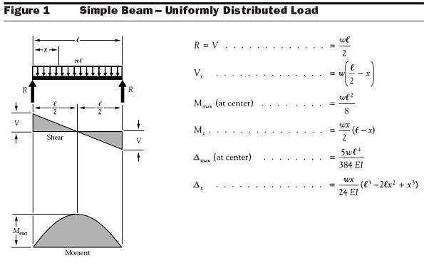
There is zero horizontal shear in the center and maximum shear force at the ends of a beam. Maximum bending moment occurs where the magnitude of shear passes through zero. Here is the graphic for a uniformly loaded beam, notice where shear passes through zero and where the maximum bending moment occurs. Look back at the pics above, same dang thing.
simplebeam.jpg
Stack all three boxes in the middle of the beam, see how the bending moment would be doubled? Always check deflection. Then check the jack to header bearing area for crushing. After that the built up column has a couple of issues. It is recieving an axial load down its' length from above while simultaneously getting a bending load from wind. What dhengr called a beam/column, you'll find in the NDS under "combined bending and axial loading". To illustrate this, take a slender stick like a yardstick, stand it on the floor and push down on it. It will accept a certain amount of load, the roof gravity load. Now while doing that push on the side of it, the wind, it just got a whole lot weaker didn't it? The more vertical, axial, load the less bending, wind, load the post can handle... and vice versa. One tall slender post is doing two things, the analysis weighs and balances that interrelationship between the two loads to make sure that the column is capable of handling both loads safely. (For you old engineers this changed in the '05 NDS. There is a new design value, Emin, to be used with columns, you can download the Supplement of Design Values on the awc.org site under "publications". It will not really change your results but is the "proper" way to do the math using an "allowable" Emin rather than an absolute value for E.)I've reinforced these columns by making them deeper or with steel sandwiched in them to form a flitch plate. I've also run a flatways "plant shelf" beam horizontally across the header between the window levels and secured it to the sidewalls, the reaction is directed through and down them. As dhengr pointed out, either way the ends are beam reactions that need to be secured as such. Since this was engineered, it points out why I as a carpenter have tried to pick up a bit of engineering along the way, more eyes.

View attachment 360

View attachment 361

View attachment 362

View attachment 363

View attachment 360

View attachment 361

View attachment 362

View attachment 363

/monthly_2011_01/shear1.jpg.2b5669a0f5d489358d9c52625745b5cb.jpg

/monthly_2011_01/shear2.jpg.9cda2f4a2d296f3952f5692c389fd2f8.jpg

/monthly_2011_01/shearmid.jpg.b39377f69f675f704f8e107db0481b06.jpg

/monthly_2011_01/shearend.jpg.9f8afc02eda94fe4105049b5dae4d401.jpg
 
Last edited by a moderator:
Definitely needs an engineer. Two questions.

1. How do they comply with braced wall requirements with that skinny corner and all of those windows?

2. Did they claim the exemption for R-38 in the ceiling?
 
Back
Top