-
Welcome to The Building Code Forum
Your premier resource for building code knowledge.
This forum remains free to the public thanks to the generous support of our Sawhorse Members and Corporate Sponsors. Their contributions help keep this community thriving and accessible.
Want enhanced access to expert discussions and exclusive features? Learn more about the benefits here.
Ready to upgrade? Log in and upgrade now.
You are using an out of date browser. It may not display this or other websites correctly.
You should upgrade or use an alternative browser.
You should upgrade or use an alternative browser.
Rafter Thrust
- Thread starter jar546
- Start date
steveray
SAWHORSE
Sifu
SAWHORSE
- Joined
- Sep 3, 2011
- Messages
- 3,318
That looks like any of a hundred frame jobs I have seen...and failed back in the day. Lots of engineering solutions have been come up with after the fact, many some variation of the strap steveray shows. I encountered this very heavily in the rural south, and saw more than a few failures where the exterior walls were blowing out. Very common in "bonus room" framing which is usually made worse by using knee walls at the exterior. Once demonstrated the issue to a builder (on a very nice home) by having him help me measure across the room at the bottom and the top plate. I asked him if he purposely installed the knee walls several inches out of plumb. This was made very apparent by the "temporary" t-posts they were using to hold up the ridge board. It was bowed so badly the nails were bending at the connection.
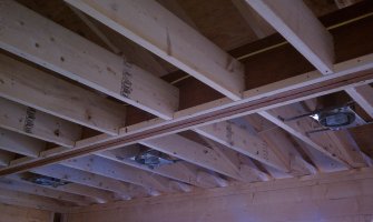
In Jar's photo a flat strap across the bottom would do it, but might ruin the finish product. Also, I rarely have seen ledger framing outside of the south, which makes a nice finish, but the ledger nails look a little far apart.
In Jar's photo a flat strap across the bottom would do it, but might ruin the finish product. Also, I rarely have seen ledger framing outside of the south, which makes a nice finish, but the ledger nails look a little far apart.
steveray
SAWHORSE
wwhitney
REGISTERED
The ceilings joists in the picture are parallel to the rafters, so it would be the next line in the table, which directs you to R802.5.2. Section R802.5.2.1 tells you the lap connections have to be the equivalent of the ceiling joist to rafter connection specified in Table R802.5.2(1).So this is what they are trying to rercreate:
Cheers, Wayne
steveray
SAWHORSE
Attachments
steveray
SAWHORSE
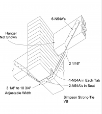
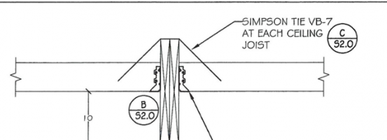
I recommend a Simpson VB-7...but it is way overkill, but you can point to it in the book, so it is easy.......You are looking at controlling about 400# if you are using the prescriptive nail connection...
View attachment 11170

VB
The VB provides lateral resistance force at the bottom of beams when installed approximately 45° or more to the vertical plane.

Never seen this used. Usually see CS-22. Almost always specified by an engineer. The dry-waller can work around it.
Sifu
SAWHORSE
- Joined
- Sep 3, 2011
- Messages
- 3,318
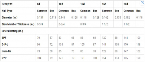
Referring to the ledger nails. I had it in my head that they should be closer, but the current codes don't give a dimension, and the code I thought they exceeded calls it 4" o/c, so these are probably fine. Ledger framing provides a much better finish, produces less squeaks, and is cheaper and quicker. JMHO.I don’t see the problem. Looks like 3 toe nails from the joist, part way into the beam web … we always do it that way …
The ledger appears to provide less than 1.5" bearing.
steveray
SAWHORSE
You mean this?Referring to the ledger nails. I had it in my head that they should be closer, but the current codes don't give a dimension, and the code I thought they exceeded calls it 4" o/c, so these are probably fine. Ledger framing provides a much better finish, produces less squeaks, and is cheaper and quicker. JMHO.

jar546
CBO
No collar ties, but if there were, they still don't count for rafter thrust.Jar, are there any collar or rafter ties above the CJ/Beam connections to prevent spread?
Sifu
SAWHORSE
- Joined
- Sep 3, 2011
- Messages
- 3,318
Yes. Back in the day in another state with a state code, they prescribed it in this table and I guess I mis-remembered it as "within 3" of the joist, so one nail under and 2 or 3 within 3" of the joist. But, I went back and can only find that it says 4" o/c. It may have come from an earlier edition, or it may be that I have been wrong all along, and current code has no distance prescription anyway with "At each joist".
jfmann77
REGISTERED
Relative to tension force from inside ends of attic floor joists, at main beam (girder).......... that resist outward thrust force from low ends of rafters;
Angled nails ("toenails").........installed to connect inside end of attic floor joists to side face of main beam........are not resisting force from attic floor joists as shear force in "normal" way considered for NDS provisions governing design shear capacity for toenails.......which is for downward-acting force due to vertical load on joists. Such nails resist tension force from floor joists mostly in withdrawal (from main beam).......and are susceptible to weakening over time with cycles of snow load on roof. For relatively small outward thrust force........such connections can work...........however, for larger houses and lower-slope roof, such connections are not adequate.
If top of beam is flush with top of floor joists, then most effective method for resisting outward thrust force from low ends of rafters is to install plywood floor sheathing......even if only 4-feet wide.........securely nailed to attic floor joists on each side of beam.
Other method that should be considered ........if main beam is available...........is to design beam to support ridge member (of roof) along with attic floor load.
Snow load and floor live load can be reduced when both design loads are combined for same load case.
Simpson connector shown in previous post surely can work...........though not really required for every joist if plywood can be installed on floor joists on each side of beam. Install strip of plywood (4-feet wide is best) on each side of beam, securely nailed to joists with 8d nails at 6-inches or less. Narrow open-strip can be provided adjacent to each side of beam to provide clear access for installation of connectors (to joist and beam)..........which could likely be spaced at every third joist or even more, depending on allowable tension capacity and required thrust force. Plywood will essentially span between connectors as deep horizontal beam.......or "diaphragm".
Other connectors can be used with same approach.
jfmann77
REGISTERED
To clarify comment in previous post about strap connectors being spaced at "every third joist or more";
Spacing may be governed by shear capacity of nails in plywood. If entire attic floor were to have plywood floor sheathing..... then design capacity of connector would govern spacing. However, if only 4-feet wide strip of plywood is provided on each side of beam..........then spacing of connectors will likely be governed by shear capacity of nails connecting plywood to floor joists that have connectors.
Spacing at every third joist could be used for moderate thrust force conditions. However, for relatively large thrust force conditions, spacing of connectors would have to be at every second joist or even at every joist...........unless more plywood were installed.
Yankee Chronicler
REGISTERED
Relative to tension force from inside ends of attic floor joists, at main beam (girder).......... that resist outward thrust force from low ends of rafters;
Angled nails ("toenails").........installed to connect inside end of attic floor joists to side face of main beam........are not resisting force from attic floor joists as shear force in "normal" way considered for NDS provisions governing design shear capacity for toenails.......which is for downward-acting force due to vertical load on joists. Such nails resist tension force from floor joists mostly in withdrawal (from main beam).......and are susceptible to weakening over time with cycles of snow load on roof. For relatively small outward thrust force........such connections can work...........however, for larger houses and lower-slope roof, such connections are not adequate.
If top of beam is flush with top of floor joists, then most effective method for resisting outward thrust force from low ends of rafters is to install plywood floor sheathing......even if only 4-feet wide.........securely nailed to attic floor joists on each side of beam.
Other method that should be considered ........if main beam is available...........is to design beam to support ridge member (of roof) along with attic floor load.
Snow load and floor live load can be reduced when both design loads are combined for same load case.
Simpson connector shown in previous post surely can work...........though not really required for every joist if plywood can be installed on floor joists on each side of beam. Install strip of plywood (4-feet wide is best) on each side of beam, securely nailed to joists with 8d nails at 6-inches or less. Narrow open-strip can be provided adjacent to each side of beam to provide clear access for installation of connectors (to joist and beam)..........which could likely be spaced at every third joist or even more, depending on allowable tension capacity and required thrust force. Plywood will essentially span between connectors as deep horizontal beam.......or "diaphragm".
Other connectors can be used with same approach.
I didn't understand anything you wrote. Something abut attic floor joists? How did you get from that to ridge beams?
Please explain you question better.
jfmann77
REGISTERED
Responding to issues in thread...........not asking question.I didn't understand anything you wrote. Something abut attic floor joists? How did you get from that to ridge beams?
Please explain you question better.
Attic floor joists generally used as rafter ties to resist outward thrust force from low ends of rafters...........that is basic condition "setting stage" for issues discussed in this thread.
However...........requirement for transferring tension force in attic floor joists.......across flush-framed attic beam that supports inside ends of attic floor joists..........is resolved if structural ridge beam can be used to support high ends of rafters..........since then there is no outward lateral force at low ends of rafters.
Of course.........ridge beam must have adequate supports.............which, in this case, could be provided by attic beam as long as attic beam has adequate design capacity to support attic floor and ridge beam at same time.


