Beniah Naylor
SAWHORSE
Wondering if anyone can explain what is going on here.
I have been trying to figure out a way to test a grounding electrode's resistance to ground in a cheap and safe way, without buying specialized equipment or energizing the electrode and measuring the amperage drawn.
The NEC does not require a properly installed Concrete Encased Electrode (Ufer) to meet any kind of resistance to ground criteria, I am doing this more in the interest of science.
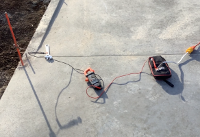
So, what I did was plug an extension cord into the temp power at at the site and run the extension cord over next to the Ufer connection point. I attached one lead of my meter to the neutral conductor of the extension cord, which is bonded to the utility neutral, which is bonded to the utility grounding system. I attached the other lead directly to the Ufer I was trying to test. I used lever style wagos to connect my leads to the wires to insure a solid connection. I then selected the "ohms" setting to measure the resistance between the Ufer and the utility grounding electrode system with the DC pulse generated by the meter passing through the earth to get from the Ufer to the utility grounding electrode system.
Going in, I was assuming that since the utility has a grounding electrode at every ground level transformer and utility pole, and that they are all bonded together by the utility's neutral wire, I was assuming that the utility's grounding electrode system is at either 0 ohms of resistance to ground or as close to 0 ohms as is feasibly possible. Therefore, any resistance on this circuit would come from the Ufer.
When I did the above experiment, my meter said that there was 0 ohms of resistance between the Ufer and the utility neutral. I left and came back the next day, still 0 ohms. There is no connection from any part of the slab to the temp power pedestal. When I unplug the extension cord, the meter reads "OL", which means no connection whatsoever. Plug it back in, 0 ohms. I calibrated my meter on a 10 ohm resister, and the meter read 10.1 ohms, which is within tolerance for that meter. When I switched to testing continuity, the meter rang like a bell. When I shoved the temp power end of the extension cord into the dirt, it had a fluctuating reading of around 500 M ohms. When I touched the concrete with the end of the cord, it measured a fluctuating 350 M ohms. It had rained 4 days before the first experiment, 5 days before the second experiment.
I did not even know that a 0 ohm resistance to ground was possible for a Ufer only the size of a house. No one else in my department can explain it either. Can anyone here explain to me:
(1) How a 0 ohm resistance through the earth is possible?
(2) Is there is a flaw in the method I am using?
I have never heard of anyone else testing a ground by measuring ohms between a known good electrode and an unknown electrode.
Any input would be appreciated. Thanks!

.PNG")

I have been trying to figure out a way to test a grounding electrode's resistance to ground in a cheap and safe way, without buying specialized equipment or energizing the electrode and measuring the amperage drawn.
The NEC does not require a properly installed Concrete Encased Electrode (Ufer) to meet any kind of resistance to ground criteria, I am doing this more in the interest of science.
So, what I did was plug an extension cord into the temp power at at the site and run the extension cord over next to the Ufer connection point. I attached one lead of my meter to the neutral conductor of the extension cord, which is bonded to the utility neutral, which is bonded to the utility grounding system. I attached the other lead directly to the Ufer I was trying to test. I used lever style wagos to connect my leads to the wires to insure a solid connection. I then selected the "ohms" setting to measure the resistance between the Ufer and the utility grounding electrode system with the DC pulse generated by the meter passing through the earth to get from the Ufer to the utility grounding electrode system.
Going in, I was assuming that since the utility has a grounding electrode at every ground level transformer and utility pole, and that they are all bonded together by the utility's neutral wire, I was assuming that the utility's grounding electrode system is at either 0 ohms of resistance to ground or as close to 0 ohms as is feasibly possible. Therefore, any resistance on this circuit would come from the Ufer.
When I did the above experiment, my meter said that there was 0 ohms of resistance between the Ufer and the utility neutral. I left and came back the next day, still 0 ohms. There is no connection from any part of the slab to the temp power pedestal. When I unplug the extension cord, the meter reads "OL", which means no connection whatsoever. Plug it back in, 0 ohms. I calibrated my meter on a 10 ohm resister, and the meter read 10.1 ohms, which is within tolerance for that meter. When I switched to testing continuity, the meter rang like a bell. When I shoved the temp power end of the extension cord into the dirt, it had a fluctuating reading of around 500 M ohms. When I touched the concrete with the end of the cord, it measured a fluctuating 350 M ohms. It had rained 4 days before the first experiment, 5 days before the second experiment.
I did not even know that a 0 ohm resistance to ground was possible for a Ufer only the size of a house. No one else in my department can explain it either. Can anyone here explain to me:
(1) How a 0 ohm resistance through the earth is possible?
(2) Is there is a flaw in the method I am using?
I have never heard of anyone else testing a ground by measuring ohms between a known good electrode and an unknown electrode.
Any input would be appreciated. Thanks!