• Welcome to the new and improved Building Code Forum. We appreciate you being here and hope that you are getting the information that you need concerning all codes of the building trades. This is a free forum to the public due to the generosity of the Sawhorses, Corporate Supporters and Supporters who have upgraded their accounts. If you would like to have improved access to the forum please upgrade to Sawhorse by first logging in then clicking here: Upgrades

18" Dia. x 42" Sonotube ?

tbz

Silver Member
Joined
Sep 10, 2010
Messages
1,252
Location
PA/NJ - Borderlands
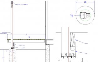
So here is the question, looking at a footing for 6x6 column & 4x4 column for a porch beam, side cut view, closeup and top view of the sonotube.

so the roof rafters run out over the header on the 6x6, that is fine by itself, the question is the 4x4 for the porch beam holding the floor joists.

The design shows the (2) bases back to back and then centered as a pair on the 18" footing, there is more than 3-1/2" of concrete from any edge of the column bases from any edge and yes both columns are not directly centered on the footing diameter.

The red vertical line is the centerline of the 18" footing/sonotube.

Based on the 2015 IRC, does anyone see an issue with the two bases sharing the footing (as offset), the loads are fine.

If the 6x6 landed off dead center and the other base was not there, would you have an issue with it.

Deck03.JPG
 
I see no problem, as sufficient projection of the footing is provided. Furthermore, given the depth to which the footing extends, a rotational failure of the pier is incredibly unlikely.
 
My only caution, Piers don’t always land as planned with posts perfectly centered. Maintain a minimum 2” projection from the edge of the 4 & 6” by 6” posts to the edge of pier.
 
My only caution, Piers don’t always land as planned with posts perfectly centered. Maintain a minimum 2” projection from the edge of the 4 & 6” by 6” posts to the edge of pier.
So, if this was a 16" diameter footing with 2-1/2" spacing all around minimum, you would accept it also?
 
The hardware has installation instructions with a minimum edge distance, if you’re concerned about the pier, use #4 for the three spirals in the first six inches. The cardboard tube shouldn’t be below grade.
 
That is only 1.8sq feet of a bearing point for the sonotube footprint. I would be more concerned about the tributary load now that you have increased loads from the decking and roof with snowload I assume?
 
That is only 1.8sq feet of a bearing point for the sonotube footprint. I would be more concerned about the tributary load now that you have increased loads from the decking and roof with snowload I assume?
My thoughts exactly but he said loading was good...must be good soil bearing...
 
I would not be concerned with the eccentric loading of the foundation.

Minimum size of footing here would be 23" dia. and the 4x4 would need to be upsized to a 6x6.
 
This is a covered porch 8' P x 16' W 2 sides exposed Front & Right Side

The ground is extremely rocky and we are hoping to not have to blast to form the basement.

We might increase to a 24" dia. depending on what we hit when digging.

Thanks for the Input - Tom
 
Why not just use a girder hanger off of the 6X6 post? Seems much cleaner and simpler, but I'm not a designer.
 
The hardware has installation instructions with a minimum edge distance, if you’re concerned about the pier, use #4 for the three spirals in the first six inches. The cardboard tube shouldn’t be below grade.
Why shouldn't the cardboard tube be below grade?
 
Why shouldn't the cardboard tube be below grade?
Theoretically it will rot away and leave a void....

IMHO, I would never write that up though. The thickness of the cardboard tube is so minor, that even if it did rot away, it would not create a substantial void that would impact the lateral stability of the footing. (This is the common sense answer, but may conflict with the code. Applying the intent, not the letter of what it says.)
 
In climates where the ground freezes you would have big problems if you poured against the earth. The irregular surfaces allow the freezing soil to grab the pier and heave it out of the ground. Also, those piers are not designed for any lateral loading since they support gravity loads only; a void would not affect performance. For something to move, you need a force to move it. (F-ma, a=F/m)
 
FYI... most of the time that I have seen someone write up the removal of forms, they point to IRC Section R408.5.

R408.5 Removal of Debris
The under-floor grade shall be cleaned of all vegetation and organic material. Wood forms used for placing concrete shall be removed before a building is occupied or used for any purpose. Construction materials shall be removed before a building is occupied or used for any purpose.

Note that this code section only identifies wood forms be removed. Although, if dug in like a tick, they will continue to argue that the last sentence, which requires removal of construction materials, would include cardboard forms.

I would further point out that the IRC has a whole section dedicated to stay in place forms. IRC Section R404.1.3.3.6.1 covers stay in place forms, but can provide further confusion for sono tubes as they do not neatly comply.

R404.1.3.3.6.1 Stay-In-Place Forms
Stay-in-place concrete forms shall comply with this section.
  1. Surface burning characteristics. The flame-spread index and smoke-developed index of forming material, other than foam plastic, left exposed on the interior shall comply with Section R302. The surface burning characteristics of foam plastic used in insulating concrete forms shall comply with Section R316.3.
  2. Interior covering. Stay-in-place forms constructed of rigid foam plastic shall be protected on the interior of the building as required by Section R316. Where gypsum board is used to protect the foam plastic, it shall be installed with a mechanical fastening system. Use of adhesives in addition to mechanical fasteners is permitted.
  3. Exterior wall covering. Stay-in-place forms constructed of rigid foam plastics shall be protected from sunlight and physical damage by the application of an approved exterior wall covering complying with this code. Exterior surfaces of other stay-in-place forming systems shall be protected in accordance with this code.
  4. Termite protection. In areas where the probability of termite infestation is "very heavy" as indicated by Table R301.2(1) or Figure R301.2(7), foam plastic insulation shall be permitted below grade on foundation walls in accordance with Section R318.4.
  5. Flat ICF wall system forms shall conform to ASTM E2634.
 
In climates where the ground freezes you would have big problems if you poured against the earth. The irregular surfaces allow the freezing soil to grab the pier and heave it out of the ground. Also, those piers are not designed for any lateral loading since they support gravity loads only; a void would not affect performance. For something to move, you need a force to move it. (F-ma, a=F/m)
The eccentric loading (loading off of center) is your lateral force.
 
Not necessarily. The deck frame is bracing the top of the footing and transferring the eccentric couple to the main building. The pier shown does not have a lateral force component.
I disagree. While your principle is solid, it is not demonstrated. The method you proposed would be outside the capabilities of the IRC, thus many would suggest an engineering design would be required. Furthermore, no tension type connection is provided between the deck and the house.
 
I disagree. While your principle is solid, it is not demonstrated. The method you proposed would be outside the capabilities of the IRC, thus many would suggest an engineering design would be required. Furthermore, no tension type connection is provided between the deck and the house.
One of us is a structural engineer and one of us is not. You can disagree but you don't seem to understand how eccentric forces are resolved.

R507.9.2 requires a lateral connection. Without a lateral connection at the main structure you would need braced or moment frames, or moment connections at the tops of all the piers. Then you would definitely have a lateral force at the tops of the piers.
I am not aware of any IRC requirement that the centroid of the posts align with the centroid of the pier. Probably because any eccentric loading is negligible. I would be hard pressed to think of a situation where you would have any net uplift at the deck pier bearing.
I'm done engaging with you redeyedfly... You have no idea who I am or what my level of expertise is.

If you want to continue with your logical fallacies, go for it. This forum is about sharing ideas and perspectives. We may not all agree, and this is not just ok, but is what we hope to have. That said, when you disagree, you do not have to make a personal attack on someone. Share your opinion and move on.

I find this post quite interesting. It includes a couple of logical fallacies.

1. Personal attacks: this type of logical fallacy is typically used to distract an opponent by attacking their character. The opponent usually tries to defend their character, thus being distracted from the actual argument at hand. A good example of this is seen typically in debates between politicians. This tactic is typically used where the holder of an opinion or position becomes aware that they cannot argue their side through logic.

2. Onus of proof: this type of logical fallacy is where one side demands that the other side prove them wrong. This establishes the conception that without onus of proof that the opinion or position is wrong, it must be right. The reality is much different, it is not a binary situation. In that circumstance, the opinion or position is neither true nor false. There is simply not enough evidence provided.

Onus of proof is where we as building officials live a lot of the time. For instance, the building inspector provides a code reference saying installation must be to manufacturer's written instructions. The onus is then on the builder to provide the instructions they are using to install the window.
 
Oh, you're the logical fallacy guy. We'll add structural engineering to the list of things you think you know but don't.
Maybe you want to try a few more straw man arguments to poke holes in arguments I'm not making.
 
Top