• Welcome to the new and improved Building Code Forum. We appreciate you being here and hope that you are getting the information that you need concerning all codes of the building trades. This is a free forum to the public due to the generosity of the Sawhorses, Corporate Supporters and Supporters who have upgraded their accounts. If you would like to have improved access to the forum please upgrade to Sawhorse by first logging in then clicking here: Upgrades

2018 IBC Required Ramp Width (1012.5.3, 1014.8)

walker.t

Registered User
Joined
Jan 10, 2024
Messages
167
Location
North Carolina
I am reviewing the requirements for required width of ramps in the 2018 IBC and am having trouble reconciling 1012.5.3 and 1014.8, am hoping someone can help clarify this for me.

1. 1012.5.3 (“Restrictions” under “Minimum Dimensions”) states, “Projections into the required ramp and landing width are prohibited.”
2. The confusion is when I look to 1014.8 (“Projections” under “Handrails”) which states, “Projections into the required width of…ramps at each side shall not exceed 4 1/2” at or below the handrail height.”
3. Both sections make reference to “required width,” I do not understand how one provision can say projections are prohibited yet another says projections are allowed.

So if I had a ramp with a required width of 48” based on occupant load, per 1012.5.3 I must provide 48” in between handrails, but 1014.8 would allow handrails to project into the 48” which would give 48” - (4.5” x 2 = 9”) = 39” between handrails.

I checked the 2018 IBC Illustrated Handbook and Building Codes Illustrated by Francis Ching, no clarification. Can someone point out what I’m missing?

Thank you.
 
Frank Chin is an incomparable illustrator, but he is not (as far as I know) empowered by the ICC or any state or local jurisdiction to interpret the code.
 
The ICC Commentary for section 1012.5.3 of the 2021 IBC reads as follows:

The purpose of not allowing ramps to reduce in width
in the direction of egress travel is to prevent a restriction
that would interfere with the flow of occupants out
of a facility. This would include ramp landings in accordance
with Section 1012.6.2. Handrails are the only
exception in accordance with Sections 1012.5.1 and
1014.8.

If I then look at 1012.5.1, I find this:

1012.5.1 Width and capacity. The minimum width and
required capacity of a means of egress ramp shall be not less
than that required for corridors by Section 1020.3. The clear
width of a ramp between handrails,
if provided, or other
permissible projections
shall be 36 inches (914 mm) minimum.

So this suggests that some projections are allowed. Next look at 1014.8, per the Commentary for 1012.5.3:

1014.8 Projections. On ramps and on ramped aisles that are
part of an accessible route, the clear width between handrails
shall be 36 inches (914 mm) minimum. Projections into the
required width of aisles, stairways and ramps at each side shall
not exceed 41/2 inches (114 mm) at or below the handrail

height. Projections into the required width shall not be limited
above the minimum headroom height required in Section
1011.3. Projections due to intermediate handrails shall not
constitute a reduction in the egress width. Where a pair of
intermediate handrails are provided within the stairway width
without a walking surface between the pair of intermediate
handrails and the distance between the pair of intermediate
handrails is greater than 6 inches (152 mm), the available
egress width shall be reduced by the distance between the closest
edges of each such intermediate pair of handrails that is
greater than 6 inches (152 mm).

The way I read it, 1012.5.1 tells me that some projections are allowed, and 1014.8 tells me that handrails are among the allowable projections.
 
The way I was taught to look and understand projections and or into the required minimum width, was that projections are based on the requirements of the Protruding objects requirements. Required minimum widths either allow the reduction of the handrail or not through an exception. Simply, stairs yes sometimes no, ramps no.

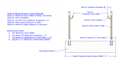
So, when teaching designers, contractors or handrail fabricators about the designing or review of a ramp, I explain to start with a 36", 48", 60" or 67" vertical cylinder, 80 inches high, whatever is required as the minimum clear width, then build outward, add the handrails on each side and the clearance distances/projections they need, up to the maximum 4.5", then what the handrails will mount to, hence either a full height wall, guard system or other and then add whatever additional width is necessary to complete the ramp's structure that becomes your footprint and the minimum structure to meet the required minimum clearance.

You don't start with the minimum width as the base structure. Here is a slide I use during lectures:

1704981335986.png
 
Frank Chin is an incomparable illustrator, but he is not (as far as I know) empowered by the ICC or any state or local jurisdiction to interpret the code.

I think you are correct, and that applies both to Ching and the coauthor Steven Winkel. The book does have the ICC logo on the cover and a “Preface from the International Code Council (ICC)” which reads in part, “This updated guide continues its long tradition of serving as a key resource for those interested in not only understanding the code, but applying it as well.” There’s nothing in the preface that specifically states that the ICC endorses the book. I’m surprised the ICC describes anything not published by the ICC as a “key resource.”

I have been disappointed with most of the “commentary” in Building Codes Illustrated, in many cases it only restates what is in the code. So instead of “commentary” I would say it’s more of a “summary.” In some cases I have thought, “Sounds like Ching has been reading the Illustrated Handbook…”

Regarding Ching’s reputation as an illustrator, I think the graphics in the earlier editions of his books were better, back when they were manually drafted and lettered by hand.
 
Yankee Chronicler and tbz,

Thank you both for your comments, I’ll need a little time to review these in detail before I comment.
 
The way I was taught to look and understand projections and or into the required minimum width, was that projections are based on the requirements of the Protruding objects requirements. Required minimum widths either allow the reduction of the handrail or not through an exception. Simply, stairs yes sometimes no, ramps no.

So, when teaching designers, contractors or handrail fabricators about the designing or review of a ramp, I explain to start with a 36", 48", 60" or 67" vertical cylinder, 80 inches high, whatever is required as the minimum clear width, then build outward, add the handrails on each side and the clearance distances/projections they need, up to the maximum 4.5", then what the handrails will mount to, hence either a full height wall, guard system or other and then add whatever additional width is necessary to complete the ramp's structure that becomes your footprint and the minimum structure to meet the required minimum clearance.

You don't start with the minimum width as the base structure. Here is a slide I use during lectures:

View attachment 12562

I'm pretty sure that's NOT what the code says.
 
So how would you design and come up with the ramp width that is required to have a specific clear width between the handrails?

I am not saying the posted method is specific to the OP's question of the interpretation, I am saying to get a base width of what needs to be in place work from the center outward, Minimum clear width "X", plus the handrails and their projections, plus then add in what is needed to support what the handrails are mounted to. The example is a work method to get the minimum width of a ramp base, that many times are not wide enough and require rework and get rejected at final inspection, rather than plan review. All over the country every day.

Many designers and architects, and even engineers seem to use typical details with 36", or other number, between handrails noted, and then the rest of the detail is not drawn to scale. The plans note widths that comply with code but do not take into account what is being installed and the projected encroachment of reductions.

The code says as the exerts are posted in the op's #01 post.

"1. 1012.5.3 (“Restrictions” under “Minimum Dimensions”) states, “Projections into the required ramp and landing width are prohibited.”"
  • Thus, measured between the handrails, no projections allowed to reduce this width (More Restrictive Requirement)
"2. The confusion is when I look to 1014.8 (“Projections” under “Handrails”) which states, “Projections into the required width of…ramps at each side shall not exceed 4 1/2” at or below the handrail height.”"
  • This is a (less restrictive requirement), that is superseded by the requirements of 1012.5.3, thus not allowed on ramps.
  • Additionally, the 4.5" maximum is still part of the requirement both noted in 1014.8, and not allowed to decrease required width,
  • but also, as designated in 1003.3.2 & 1003.3.3 for protruding objects.
  • Thus, build outward for the projection, not inward.
It might seem like the code does not say that and a conflict in the OP's post, but the more restrictive over rules the lesser, does it not?

Is this no different than both 2010ADA & A117.1 allowing nosing projections to be a maximum of 1.5", but since the IBC only allows 1.25", thus the more restrictive is the number, y/n?

Been working on plan reviews with metal fabricators for almost 30 years now, and ever since then, those that review ramp width and use this process, have over a 95% positive result in having the design firm, re-design the ramps for proper widths when brought in before the concrete is poured.
 
Handrails may intrude into the clear width established by occupant load, but there must be at least 36" clear between handrails.
Paul - Question,

How do you get there with 1003.3.4 Clear Width?

I have had many a client flagged in the past for handrail projecting into a ramp width over 36-inches between handrails, that has a designated larger required clear width than was between the handrails, but not when you take the measurement above the handrails to the guards, and per 1003.3.4, not having an exception for handrails specifically.

Are not handrails considered protruding objects, per code?
 
So how would you design and come up with the ramp width that is required to have a specific clear width between the handrails?

If there is a requirement to have a specific clear width between handrails, obviously I would design a ramp with at least that clear distance between the handrails.

Where does the IBC, A117.1, or the ADA specify a minimum clear distance between handrails? The only specific requirement I found is that after allowances are made for permissible protrusions, accessible ramps must have not less than 36 inches clear between the handrails. But not all ramps are for accessibility.
 
First off, I checked the 2021 IBC online with the PDF of the 2018 IBC I have and both 1012.5.3 and 1014.8 are the same in both editions, so a 2021 IBC commentary would apply to the 2018 IBC.

The ICC Commentary for section 1012.5.3 of the 2021 IBC reads as follows:

If I then look at 1012.5.1, I find this:

So this suggests that some projections are allowed. Next look at 1014.8, per the Commentary for 1012.5.3:

The way I read it, 1012.5.1 tells me that some projections are allowed, and 1014.8 tells me that handrails are among the allowable projections.

I agree with Yankee Chronicler’s thought process in how 1012.5.1 states that some projections are allowed and how 1014.8 tells us that handrails are one of the allowable projections. But I still don’t see why 1012.5.1 mentions permissible projections into the ramp width and then 1012.5.3 takes that away.
 
I am not saying the posted method is specific to the OP's question of the interpretation, I am saying to get a base width of what needs to be in place work from the center outward, Minimum clear width "X", plus the handrails and their projections, plus then add in what is needed to support what the handrails are mounted to. The example is a work method to get the minimum width of a ramp base, that many times are not wide enough and require rework and get rejected at final inspection, rather than plan review. All over the country every day.

The code says as the exerts are posted in the op's #01 post.

"1. 1012.5.3 (“Restrictions” under “Minimum Dimensions”) states, “Projections into the required ramp and landing width are prohibited.”"
  • Thus, measured between the handrails, no projections allowed to reduce this width (More Restrictive Requirement)
"2. The confusion is when I look to 1014.8 (“Projections” under “Handrails”) which states, “Projections into the required width of…ramps at each side shall not exceed 4 1/2” at or below the handrail height.”"
  • This is a (less restrictive requirement), that is superseded by the requirements of 1012.5.3, thus not allowed on ramps.
  • Additionally, the 4.5" maximum is still part of the requirement both noted in 1014.8, and not allowed to decrease required width,
  • but also, as designated in 1003.3.2 & 1003.3.3 for protruding objects.
  • Thus, build outward for the projection, not inward.
It might seem like the code does not say that and a conflict in the OP's post, but the more restrictive over rules the lesser, does it not?

Is this no different than both 2010ADA & A117.1 allowing nosing projections to be a maximum of 1.5", but since the IBC only allows 1.25", thus the more restrictive is the number, y/n?
I agree with tbz noting that the more restrictive requirement in 1012.5.3 must be used regardless of what 1012.5.1 says. I also agree with the general concept of starting with the required clear width and working out.

And most definitely, the more restrictive requirement for nosing projection in the IBC would be applied. I would like to think that the IBC is internally consistent so I don’t understand why the IBC would have a less restrictive requirement for projections into the required width of ramps in 1014.8 and at the same time prohibit projections per 1012.5.3. I know I’m safe if I comply with 1012.5.3 (no projection into the required width,) I guess I just would like to know what I’m overlooking so I can resolve the apparent discrepancy.
 
Many designers and architects, and even engineers seem to use typical details with 36", or other number, between handrails noted, and then the rest of the detail is not drawn to scale. The plans note widths that comply with code but do not take into account what is being installed and the projected encroachment of reductions.

Typical details as tbz describes are a mistake. Years ago I heard that architects should never use the term “per code” on their drawings, they should state the requirement of the code - part of their job is to communicate the specific requirements of a code-compliant project. Typical details may be a starting point but they need to be updated for the project. I was reviewing structural drawings that had a shear wall schedule with five shear wall types, I’m looking at the plans and I found SW1, SW2, and SW3 but no SW4 or SW5. So, was I to assume that SW4 and SW5 should have been removed from the schedule, or did someone fail to correctly notate the plan? So there’s a request for information that could have easily been avoided - it saved the structural engineer a little time by not having to update the schedule but costs others time later on. I once reviewed drawings for a three-story building with no information at all about stair riser and tread sizes. I asked the architect, “How are they supposed to build these stairs without knowing the intended tread and riser sizes?” He said, “Oh, they’ll build it to code.” Crazy! The irony was that the builder, who had lots of experience with residential projects but very little commercial experience, did indeed build the stairs “to code” but to the residential code and the stairs had to later be removed and rebuilt to meet the commercial code.
 
Handrails may intrude into the clear width established by occupant load, but there must be at least 36" clear between handrails.

But when that clear width is the “required width” (based on the occupant load) 1012.5.3 says that no projections are allowed into the “required width” - this would include handrails, no?
 
I agree with tbz noting that the more restrictive requirement in 1012.5.3 must be used regardless of what 1012.5.1 says. I also agree with the general concept of starting with the required clear width and working out.

And most definitely, the more restrictive requirement for nosing projection in the IBC would be applied. I would like to think that the IBC is internally consistent so I don’t understand why the IBC would have a less restrictive requirement for projections into the required width of ramps in 1014.8 and at the same time prohibit projections per 1012.5.3. I know I’m safe if I comply with 1012.5.3 (no projection into the required width,) I guess I just would like to know what I’m overlooking so I can resolve the apparent discrepancy.
Ramps are different than stairs, as there are normally very few ramps that are not part of the accessible route.

Per 1003.3.4 Clear width. Protruding objects shall not reduce the minimum required width of accessible routes.

There are no exceptions listed for 1003.3.4,

Thus, the accessible route does not allow reduction by a protruding object, handrails are protruding objects, and unless I am missing something unless you can provide documentation that the ramp is not part of an accessible route, we loop back to 1003.3.4 clear width not allowing it.

This is what has been flagged by multitudes of AHJ across the country for many years, for measuring between the handrails on ramps.
 
Before I knew that the IBC addressed protruding objects, I was familiar with the requirements in ADA 307.5 and A117.1 307.5 which both say that protruding objects cannot reduce the clear width required for accessible routes, also no exceptions stated there.

I can’t readily think of an example where a ramp in new construction would not be considered part of an accessible route.
 
Typical details as tbz describes are a mistake. Years ago I heard that architects should never use the term “per code” on their drawings, they should state the requirement of the code - part of their job is to communicate the specific requirements of a code-compliant project. Typical details may be a starting point but they need to be updated for the project. I was reviewing structural drawings that had a shear wall schedule with five shear wall types, I’m looking at the plans and I found SW1, SW2, and SW3 but no SW4 or SW5. So, was I to assume that SW4 and SW5 should have been removed from the schedule, or did someone fail to correctly notate the plan? So there’s a request for information that could have easily been avoided - it saved the structural engineer a little time by not having to update the schedule but costs others time later on. I once reviewed drawings for a three-story building with no information at all about stair riser and tread sizes. I asked the architect, “How are they supposed to build these stairs without knowing the intended tread and riser sizes?” He said, “Oh, they’ll build it to code.” Crazy! The irony was that the builder, who had lots of experience with residential projects but very little commercial experience, did indeed build the stairs “to code” but to the residential code and the stairs had to later be removed and rebuilt to meet the commercial code.

In BOCA days, the BOCA Basic Building Code under "Construction Documents" specifically stated that using terms such as "per code" were not a substitute for specific information showing code compliance.

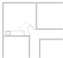
That said, having the design professional re-state the code requirements on the drawings is, IMHO, no better than just writing "per code." For example, these days most drawing sets for medium to large commercial (meaning IBC rather than IRC) buildings include a sheet that reproduces most of the maneuvering clearance diagrams out of A117.1. Some time ago, I remember reviewing a set of drawings that included such a boilerplate sheet. It was for a doctor's office -- and one of the exam rooms had the door in a corner, set on the diagonal, so that it was impossible to provide the required latch side clear space. Yes, the architect included the diagram, but then he specifically designed a building that didn't comply with the information that he reproduced in the construction documents. It looked pretty much like this (except that on the floor plan sheets he didn't show the dashed line for the clear maneuvering space at the doors):

1705030123314.png

I HATE it when architects regurgitate the code on the drawings. I already HAVE the code -- it's sitting right beside me while I review the drawings, so I don't need it. And the contractor shouldn't need to have the code regurgitated on the drawings. His job is to build what's shown on the construction documents, so just draw what needs to be built.
 
Thank you for sharing about the BOCA comment.

I agree with everything you say here. I used the wrong term when I said “they should state the requirements of the code.” By saying “state” I wasn’t suggesting that reproducing diagrams straight from A117.1 is acceptable. What I meant is that whatever the architect draws must incorporate the requirements of the code into those drawings. For example, a handrail would have a specific height called out and that height should be within the allowable range for handrail height, there will not be a note that says, “See X/A1” and then that detail is only a reproduction of A117.1 Figure 505.4 (“Handrail Height”) and other diagrams related to handrails.

I have seen the use of diagrams reproduced from the code on architect’s drawings. I just checked a set of drawings a client sent me for an interior renovation of a 3-story building. A1.0 has a reproduction of toilet grab bars from A117.1 Figure 604.5.1 and Figure 604.5.2. The architect didn’t even put a note on the plans directing the reader to this diagram. Funny thing is that the diagram is titled “ADA Mounting Heights” but the vertical grab bar he shows is required by A117.1, not the ADA! Floor plans call out stairs as “Maximum 7” Riser” - no information on tread depth - total stair run isn’t even dimensioned. Handrails are only labeled with a note reading, “1 1/2” Diameter Handrail” - not a word about mounting height or extensions.

Your experience with the architect who didn’t produce a plan complying with door maneuvering clearances he put on the drawings is kind of sad, like, how did he miss that? Years ago I started showing the door clearances on the plans like your drawing shows, a bit of in-process quality assurance and something to make things a little easier for the plans reviewer.
 
Having worked for many architecture firms as a design consultant over the past 40+ years, I can only smile when you refer to "the architect". What I saw was AutoCAD and now REVIT basically removed the architect with experience from the drawing process, and substituted "cad operators", some of whom may be registered architects. They keep busy early on by laying out sheets and adding lots of boilerplate. Then, a high school for instance which used to be 40 or 50 sheets, has become 1000. "The architect" can't possibly review and coordinate a 1000 sheets. Hopefully it will change but a lot of the GC foremen agree that the drawings today are much worse coordinated then when hand drawn (and in ink often!)

So you're right, the architects and drafters and force writers are not quite up to the task today. Sure, the starkitects get enough fee so they can do better. Some regional firm cranking out high schools for, if lucky, 5 1/2% of the construction, just aren't paid enough.
 
  • Like
Reactions: tbz
Over the past 15 years or so, I’ve seen many multifamily architecture fees under 1.5% of construction budget. I would guess many people in the industry don’t realize how tight it is.
 
Having worked for many architecture firms as a design consultant over the past 40+ years, I can only smile when you refer to "the architect". What I saw was AutoCAD and now REVIT basically removed the architect with experience from the drawing process, and substituted "cad operators", some of whom may be registered architects. They keep busy early on by laying out sheets and adding lots of boilerplate. Then, a high school for instance which used to be 40 or 50 sheets, has become 1000. "The architect" can't possibly review and coordinate a 1000 sheets. Hopefully it will change but a lot of the GC foremen agree that the drawings today are much worse coordinated then when hand drawn (and in ink often!)

So you're right, the architects and drafters and force writers are not quite up to the task today. Sure, the starkitects get enough fee so they can do better. Some regional firm cranking out high schools for, if lucky, 5 1/2% of the construction, just aren't paid enough.
I had the opportunity to review a set of drawings from a starkitect’s firm, project was a relatively small contemporary single-family residence, drawings were done in Revit. It’s a big firm, has done tons of work, so I would think they’d have funds for proper Revit training and training of their staff. Here are a few of the things the “CAD operators” missed and then the architect who sealed the drawings (sealing architect was a partner in the firm, not the starkitect):

1. Multiple, random dimensions on the floor plans taken to the finish face of the wall. I don’t know if dimensioning in Revit is done manually or by the application, but these were not critical dimensions, everything should have been dimensioned to face of framing member. So the contractor had to subtract for the wall finish, if they even noticed.
2. Modeling anomalies in section, like a handrail at the second floor shooting out over the stairwell opening or the steel stair stringers extending through the second floor.
3. A slab edge detail on the structural sheets that doesn’t match how the architect drew their section. Which one is correct? Hopefully the architect knew when the contractor called them up to ask for clarification. But the architect’s final review should have caught this, this is simple, basic coordination.
 
I'd agree on a one family dwelling, they ought to be able to check and coordinate drawings.

I learned AutoCAD when there were a few dozen commands. Had to write a basic program (remember basic?) to do that. I was able to keep up with new editions at least till 2010. Could not for the life of me make the transition to Revit - owned it and had on my computer for 10+ years. Retired. People long in the tooth generally don't do well with fast changing technology. I know one colleague who still drafts by hand. Of course exceptions.
 
For whatever reason I’ve never been excited by BIM, I’m OK using separate applications for drafting and modeling. Part of me envies those who still draft by hand.
 
Top