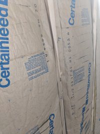
• Welcome to the new and improved Building Code Forum. We appreciate you being here and hope that you are getting the information that you need concerning all codes of the building trades. This is a free forum to the public due to the generosity of the Sawhorses, Corporate Supporters and Supporters who have upgraded their accounts. If you would like to have improved access to the forum please upgrade to Sawhorse by first logging in then clicking here: Upgrades

Another vapor barrier question

Getting close. Below is slashed Kraft paper. I'll post a picture of the NEMA OS 4 boxes later. Pricey but easy and seem to do a good job. They do have a foam gasket around cable entrances, but a dab of caulk or foam probably would help. One benefit is the strain relief seems much better than on the lower cost plain plastic boxes.
 

Attachments

  • PXL_20231018_124302147.jpg
    PXL_20231018_124302147.jpg
    2.8 MB · Views: 4
NIST (the National Institute for Standards and Technology) used to distribute a free program called MOIST, which was used to model building walls and calculate where within the assembly the dew point fell. That's the critical concern with vapor barriers -- you don't want the dew point to occur within the insulation, or any moisture vapor that sneaks through the vapor barrier will condense in the insulation.

Using graph paper and drawing the wall section to scale, and plotting the temperature change within each material in proportion to the overall temperature difference between interior and exterior, you can do the same thing manually. With two separate insulated walls, it might be informative to draw this up and see what the temperature change graph looks like.
 
Since these walls are 12" of fibreglass, I'd expect that graph to be a pretty straight line.

That's the critical concern with vapor barriers -- you don't want the dew point to occur within the insulation
Agreed - to a point. With foam - either solid or with a couple of inches to exterior (in a heating climate) the dew point must be within the foam to not cause moisture problems. And in my 12" of fibreglass, the dew point must be within it, but no surface. You really want to avoide a surface in a wall or roof - like the inside of sheathing - from being below the dewpoint. The double vapor barrier is the concern the second one may become that condensing surface.

Unless it's masonry, and then it doesn't matter so much. Block wall, foam both sides, shouldn't have a moisture problem.
 
Since these walls are 12" of fibreglass, I'd expect that graph to be a pretty straight line.

No.

Every component of a wall assembly has some R-value. To map the heat loss, you have to account for everything in the wall. And in this case there isn't a single 12-inch batt, there's an existing wall with unspecified thickness batts, then a new, inner wall with 8-inch batts. There's presumeably an air space between them, and that air space (believe it or not) has an R-value. So does the interior finish (sheetrock?), and so does whatever forms the outer face of the existing wall. The MOIST calculator from NIST even included an R-value for the still air layer at the outer face of the exterior siding.

Here's an example of a table the provides some of the values used. Note that they list an R-value for the air film on the interior face as well as for the exterior face. Curiously, this table doesn't include gypsum wallboard. You could use plaster sheets, I suppose, but I would look for a different table that actually lists sheetrock. This is just an example: https://efficiencymatrix.com/building-material-r-values/

Take a common house exterior wall (old style), for example:

Indoor air film = 0.14
1/2" GWB = 0.075
5-1/2" batt insulation = 19
1/2" plywood sheathing = 0.10
Vinyl siding - 0.009
Outdoor air film = 0.04

So the total R-value of the wall is the sum of all these materials ==> 19.364

Assume an indoor temperature of 70 degrees F and an exterior temperature of 0 degrees F. That makes delta T 70 degrees. Divide that by 19.364 and we get a temperature change of 3.615 degrees per R-1. The temperatures at each interface are computed proportionally. When its drawn graphically, you can put the temperature on the vertical (Y) axis. Take the dew point, extend a horizontal line across from that temperature on the Y axis, and it shows you where in the wall the moisture will start to condense.
 
Interesting. I'll check out the calculators.

And in this case there isn't a single 12-inch batt, there's an existing wall with unspecified thickness batts, then a new, inner wall with 8-inch batts.
My wall is 2x4 16 o. c. with R13 batts; 5 1/2" R19 batts horizontal, no framing; and then another 2x4 16 o.c. with R13 batts. So pretty close to same density through the wall. Of course the wall changes at the inner and outer surfaces. I'm sure the slashed kraft paper introduces a blip in the graph.
 
Since you posted Clayton NJ as your "Home Base" then if you are in my backyard (Philly) then we are in Climate Zone 5, Mixed Humid and I believe the current thinking is to not have a vapor barrier so any captured moisture can move both to the interior AND exterior.
Not sure i completely understand your foundation description with the SIPS
 
Clayton New York. Zone 6. Regularly below 0 F and dry as hell. Interior warmer air with much more moisture is the issue. That's why I have been meticulous on air vapor barrier. Butyl tape on rafters because of t&g ceiling. Every seam in poly taped. A little fanatical.
 
Interesting. I'll check out the calculators.


My wall is 2x4 16 o. c. with R13 batts; 5 1/2" R19 batts horizontal, no framing; and then another 2x4 16 o.c. with R13 batts. So pretty close to same density through the wall. Of course the wall changes at the inner and outer surfaces. I'm sure the slashed kraft paper introduces a blip in the graph.

And how much physical space between the two 2x4 walls? If it's less than the full 5-1/2" of the R-19 batts, then the batts aren't giving you R-19.
 
And how much physical space between the two 2x4 walls? If it's less than the full 5-1/2" of the R-19 batts, then the batts aren't giving you R-19.
12" wall leaves 5". Sure looks like the compression is spread across all three layers.

I don't know how the R is measured but I have to believe the R19 batts are providing more insulation with no framing than if between 2x6s.

Compressing a 3 1/2 inch R13 to 2 1/2" reduces it to R10. Approx 29% compressed reduces R by 23%. I'm compressing it by just 5%, so maybe 0.5 R reduction. Insignificant.

Plus, is it even more than a 12" batt? R38? I don't know.
 
Top