• Welcome to The Building Code Forum

    Your premier resource for building code knowledge.

    This forum remains free to the public thanks to the generous support of our Sawhorse Members and Corporate Sponsors. Their contributions help keep this community thriving and accessible.

    Want enhanced access to expert discussions and exclusive features? Learn more about the benefits here.

    Ready to upgrade? Log in and upgrade now.

Can you read architect? clarify this footing/pier is frost protected?

Wstubbs

REGISTERED
Joined
Nov 7, 2023
Messages
79
Location
Smithville MO
I am looking at the text on the top of the page. Before I get clarification from the gc, can anyone decipher this? At first review i thought it was a typo, now i'm thinking its a 12" deep footing with a 24" slab on top.. that will give a 36" frost protection(my area).. i just emailed the architect for clarification or to send a cross section... just thought it was worded a little strange
 

Attachments

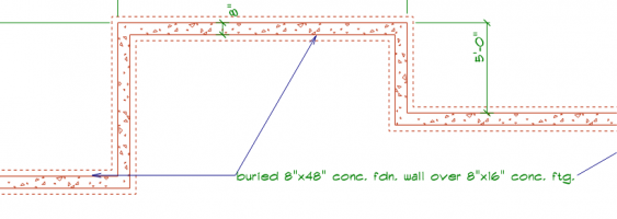
The way I am reading it, the concrete goes into the ground 12". There is a 24"x 24" x 24" cube of concrete that is exposed above ground. This occurs on 2 piers out of 5 total piers. The other 3 piers are of unknown construction (no "typical" or "typ." callout, or arrow pointing to them).
1715972325326.png

On the continuous footing, they described the foundation wall as "buried", but they did not also describe the piers (above) using the word "buried" - -so did they intend to have the piers not buried?
1715972518310.png
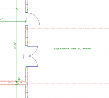
To the right there is a slab with doors that open onto it, and the slab is described as suspended.
So there's some kind of grade changes occurring in and around the house.

1715972704492.png


Unless other sections, details, notes, or elevation callouts were provided, IMO it is not possible to discern how much or how far the foundation is below grade.
 
Last edited:
I think your understanding of the intent is correct, but it is very poorly worded.

First, what's the surrounding grade elevation, and what's the top of pier elevation? Unless the piers are exactly flush with grade, this configuration will not provide 36 inches of frost depth protection. This appears to be for a residence, so probably wood construction. If so, I expect that the top of pier is going to have to be at least 8 inches above grade.

Second, where are the rebars? It could be read that they are in the footing, but it could equally be read that they are in the pier.

No mention of vertical rebars to pin the piers to the footings.
 
I thought it applied to all five and that top of pier was at grade for a deck. Looks like a 6x6 centered on pier. Wouldn't that be OK? PT 6x6 at grade?
 
I thought it applied to all five and that top of pier was at grade for a deck. Looks like a 6x6 centered on pier. Wouldn't that be OK? PT 6x6 at grade?

Sure, I also assume that it applies to all five piers -- but the arrows specifically point to only two, so assumptions about the other three are assuming a fact not in evidence.

Yes, if the deck posts are pressure treated the piers can be flush with grade. Maybe the post material is shown elsewhere in the plans. Maybe the finished grades are shown elsewhere. We don't know anything from this partial drawing.
 
Where I live, the building department would just call or email and ask what I meant. It's also sheet 5 so were 1 through 4 and any subsequent not a part of the submittal?

In 40+ years I've never seen a set of drawings that didn't have careless drafting errors. It's not getting better.
 
Where I live, the building department would just call or email and ask what I meant. It's also sheet 5 so were 1 through 4 and any subsequent not a part of the submittal?

In 40+ years I've never seen a set of drawings that didn't have careless drafting errors. It's not getting better.

It's not getting any better, IMHO, because we (as a profession) are not holding architects and engineers accountable. As to calling or e-mailing for clarification, that's of zero help if a problem arises down the road and the case ends up in court. The code says:

Construction documents shall be of sufficient clarity to indicate the location, nature and extent of the work proposed and show in detail that it will conform to the provisions of this code and relevant laws, ordinances, rules and regulations, as determined by the building official.

The code does NOT say, "The construction documents may be sufficiently confusing that the building official must call the architect to figure out what he/she meant." The code says we must approve the construction drawings, in writing or by stamp. I don't know any effective, legally-binding way to incorporate "Subject to what the architect told me over the phone:" into a set of approved construction documents. If I can't see on the drawings, clearly and unequivocally, what the contractor is supposed to build, I should not approve the drawings.

We've just seen two possible interpretations of what the sample drawing called for. I thought it referred to the footing and the pier both being below grade. Yikes read it to mean the footing will be below grade and the pier will be above grade. If it gets approved the way it appears above, who knows which way the contractor will understand it?
 
Where I live, the building department would just call or email and ask what I meant. It's also sheet 5 so were 1 through 4 and any subsequent not a part of the submittal?

In 40+ years I've never seen a set of drawings that didn't have careless drafting errors. It's not getting better.
IMHO it's only getting worse because it's so easy for them to cut and paste details that in many cases what we see detail does not correspond to the callout for the detail. I had one today at for the callout was 24" tall and 36" wide yet by looking at it on the drawing it was taller than it was wide? I scaled it and it was actually 36" tall and 24" wide so which is correct? For obvious reasons it was returned for clarification!
 
IMHO it's only getting worse because it's so easy for them to cut and paste details that in many cases what we see detail does not correspond to the callout for the detail. I had one today at for the callout was 24" tall and 36" wide yet by looking at it on the drawing it was taller than it was wide? I scaled it and it was actually 36" tall and 24" wide so which is correct? For obvious reasons it was returned for clarification!

As an architect, the key to successful cut-and-paste details in CAD templates is to make them either applicable to all situations (ADA standard details are a good example), or in the case of a footing, provide generic dimensions “X, Y, Z”, etc., then leave a big blank dimension table to fill in with highlighted colors based on site-specific information.
For example, if there was a spot footing detail, it might have dimension X for bottom of footing to top of finish grade.
Then the table lists X as 36”; or maybe it lists X as “min. 12” or per geotechnical report, whichever is greater”. But the point is, every new project has to start from the template, not from the previous project, otherwise you’ll accidentally carry previous site-specific info to the new project site.
 
i finally got a correct revision, explicitly stating 36" frost depth... all the wording stayed the same
"24" high pier + 12" conc. ftg =36" deep (frost line)"
i feel like have #+#=# was calling me a dumbass... but hey.. everyone else agreed it was not explicitly clear.. so oh well
 
i finally got a correct revision, explicitly stating 36" frost depth... all the wording stayed the same
"24" high pier + 12" conc. ftg =36" deep (frost line)"
i feel like have #+#=# was calling me a dumbass... but hey.. everyone else agreed it was not explicitly clear.. so oh well

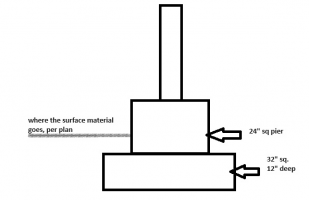
See the section view Mark Handler posted. The way it's worded on the plan view you showed only works if the finished grade is even with the tops of the piers, or the piers are actually underground. Have you checked a site plan for grading? IMHO (not strictly from a code perspective, but based on 50 years as an architect) is that there should be a site plan that shows finished grades (this is required by the IBC and, IIRC, the IRC), and the foundation plan should indicate the bottom of footing elevation (relative to the site datum and grading) for each individual footing and for each segment of continuous footings.

That's just the way it was done when I started out. Now? It's rare to find any architect or engineer who wants to spend the time to do their job. They kick that can down the road, to the contractor. Pity the poor inspector. You show up for a footing inspection, the hole has already been excavated, so how can you possibly know if the bottom of footing is going to be below the frost line?
 
The word "deep" is not well defined. None of us responding to this thread have seen the other 4 pages of plans.
In absence of any other information about finish grades and finish floor/deck elevations, one could easily presume that "12" deep" means the bottom of footing is only 12" below finish grade.

You don't need to feel like a dumbass. But it's probably OK to plan check as if the construction crew reading the plans will be dumbasses, requiring basic clarity on "how far down do I need to dig a hole"?


1716332758839.png
 
The word choice is interesting in that the 24" square section says 24" high, but the 32" square section says deep. One would logically conclude that the word choice is intentional and the 24" high means above grade and the 12" deep is below grade.

I'd ask for a detail to ensure clarity.
 
The word "deep" is not well defined. None of us responding to this thread have seen the other 4 pages of plans.
In absence of any other information about finish grades and finish floor/deck elevations, one could easily presume that "12" deep" means the bottom of footing is only 12" below finish grade.

You don't need to feel like a dumbass. But it's probably OK to plan check as if the construction crew reading the plans will be dumbasses, requiring basic clarity on "how far down do I need to dig a hole"?


View attachment 13473
I did not see the depth, that is why it is drawn in ambiguity.
 
IRC uses depth, deep, and thickness interchangeably for the vertical dimension of footing. Probably would help it it used on term. IBC same.

there should be a site plan that shows finished grades (this is required by the IBC and, IIRC, the IRC)
Could some point me to that in IRC? I found requirement for a site plan or plot plan "showing the size and location of new construction and existing structures on the site and distances from lot lines." but nothing on grade.
 
IRC uses depth, deep, and thickness interchangeably for the vertical dimension of footing. Probably would help it it used on term. IBC same.


Could some point me to that in IRC? I found requirement for a site plan or plot plan "showing the size and location of new construction and existing structures on the site and distances from lot lines." but nothing on grade.

It's an extrapolation. You are referring to section R106.2:
R106.2 Site plan or plot plan. The construction documents
submitted with the application for permit shall be accompanied
by a site plan showing the size and location of new construction
and existing structures on the site and distances from lot
lines. In the case of demolition, the site plan shall show
construction to be demolished and the location and size of
existing structures and construction that are to remain on the
site or plot. The building official is authorized to waive or
modify the requirement for a site plan where the application
for permit is for alteration or repair or where otherwise
warranted.

Strictly speaking, that section (by itself) does not require contours or spot elevations. BUT ... Section R106.1.1 requires:

R106.1.1 Information on construction documents.
Construction documents shall be drawn upon suitable material.
Electronic media documents are permitted to be submitted
where approved by the building official. Construction documents
shall be of sufficient clarity to indicate the location,
nature and extent of the work proposed and show in detail that
it will conform to the provisions of this code and relevant laws,
ordinances, rules and regulations, as determined by the building

official.

If I don't have a grading plan, how can I determine from the drawings that the foundations will extend to or below the frost line?

In addition:

R401.3 Drainage. Surface drainage shall be diverted to a
storm sewer conveyance or other approved point of collection
that does not create a hazard. Lots shall be graded to drain
surface water away from foundation walls. The grade shall fall
not fewer than 6 inches (152 mm) within the first 10 feet (3048
mm).

If I don't have grading information, how can I determine -- prior to issuing a permit -- that the drainage will comply?
 
A note on the drawing or a section showing that footings are below frost depth. And I've just noted that drains led to daylight and never questioned.

I feel sorry for you that you think everyone is trying to break the law and not comply with code.
 
Back
Top