• Welcome to The Building Code Forum

    Your premier resource for building code knowledge.

    This forum remains free to the public thanks to the generous support of our Sawhorse Members and Corporate Sponsors. Their contributions help keep this community thriving and accessible.

    Want enhanced access to expert discussions and exclusive features? Learn more about the benefits here.

    Ready to upgrade? Log in and upgrade now.

catheral cielings ridge beam

Rider Rick said:
What happens when you approve something that fails and someone gets hurt God forbid.
Sounds like the OP needs to verify the connection details, or add ties.....
 
GBrackins said:
I guess I'm confused, could someone point me to the section of the 2009 IRC that requires metal connectors for a prescriptive rafter to ridge connection? Thanks!
It doesn't, but if you do not follow the prescriptive requirement of ties, you need to, per engineering standards show how you are preventing the "spread" of the RR and the reactions at the connection points
 
Basic engineering principle

A tie, structural tie, or strap, is a structural component designed to resist tension. It is the opposite of a strut or column, which is designed to resist compression. Ties may be made of any tension resisting material. In wood frame construction they are generally made of galvanized steel. Wood framing ties generally have holes allowing them to be fastened to the wood structure by nails or screws. The number and type of nails are specific to the tie and its use. The manufacturer generally specifies information as to the connection method for each of their products. Among the most common wood framing ties used is the hurricane tie or seismic tie used in the framing of wooden structures where wind uplift or seismic overturning is a concern.

Rafter ties are designed to tie together the bottoms of opposing rafters on a roof, to resist the outward thrust where the roof meets the house ceiling and walls. This helps keep walls from spreading due to the weight of the roof and anything on it, notably wet snow. In many or most homes, the ceiling joists also serve as the rafter ties. When the walls spread, the roof ridge will sag. A sagging ridge is one clue that the home may lack adequate rafter ties. Rafter ties form the bottom chord of a simple triangular roof truss. They resist the out-thrust of a triangle that's trying to flatten under the roof's own weight or snow load. They are placed in the bottom one-third of the roof height. Rafter ties are always required unless the roof has a structural (self-supporting) ridge, or is built using engineered trusses. A lack of rafter ties is a serious structural issue in a conventionally framed roof.

You can also use a buttress as in gothic architecture to resist the spread of roof/walls
 
so then if you toe-nail plumb cut rafters to a ridge board with a collar ties ran under the ridge board attached to the sides of the rafters and you provide ceiling joists/rafter ties then you're good?
 
GBrackins said:
so then if you toe-nail plumb cut rafters to a ridge board with a collar ties ran under the ridge board attached to the sides of the rafters and you provide ceiling joists/rafter ties then you're good?
Yes, based on the size and location of the ties and fasteners. Talk with your Structural engineer....
 
Sorry, I guess I am confused, y'all have fun with that.

But if you can calculate a ridge beam to carry the load, why does outward thrust on the bearing walls come into play? Would it not be neutral? Not trying to be argumentative, just thinking the properly sized ridge will support the loads without applying additional thrust on the exterior bearing wall.
 
Once again, you guys are flying off on tangents

to put it simple

you need ties or you need engineering...

That may include designing a ridge beam, that may include metal connectors but the code is clear

Ties or engineering design.
 
Last edited by a moderator:
Because you are designing it like a floor the same way you would if it was less than 3/12. The ceiling joists and collar ties resist thrust in both directions. If you take them away the roof must act like a floor and be self supported including a ridge beam that Is sized as a girder and rafters that are sized as joists. The "joists" must have a ledger strip or mechanical connection (hanger) because the entire roof assembly must be self suppoting like a floor.

The ridge beam must be supported by a post that carries the load to the foundation. You can use a ridge beam that sits under the ridge board to support if you wish but it looks kind of funny.
 
R802.6-"The ends of each rafter or ceiling joist shall have not less than 1/12" bearing on wood or metal" That being said I think thats a stretch for opposing rafters when proper rafter ties are installed.
 
I don't see where a metal connector is required to be used with a structural ridge as long as bearing is met. Although some might require a stamped engineered design for a structural ridge, I generally don't, and approve them using "standard engineering practice". Meaning, if the ridge beam is calculated properly for loading by the supplier, or sized properly as a built-up-beam by the contractor, I am comfortable approving the roof assembly with or without metal connectors.
 
WFCM does provide limited prescriptive ridge beam spans for given loads if you want to use them. It is a nice tool to trot out when trying to illustrate the difference between a ridge board and ridge beam. Otherwise I call it like this: Structural ridge or rafter ties. I do use the WFCM for available support spans for ridges. I agree with Yankee, to a point. I will sometimes accept a member report if I can verify (or decipher) the information on it.
 
Yankee said:
I don't see where a metal connector is required to be used with a structural ridge as long as bearing is met. Although some might require a stamped engineered design for a structural ridge, I generally don't, and approve them using "standard engineering practice". Meaning, if the ridge beam is calculated properly for loading by the supplier, or sized properly as a built-up-beam by the contractor, I am comfortable approving the roof assembly with or without metal connectors.
How about the ceiling or collar tie question? not the metal connector question?
 
Where the 2006 IRC is applicable, I would direct attention to R802.3.1 including Table R802.5.1. referenced therein. This table gives prescriptive fastening requirements for the heel joint connections for ceiling joists installed as rafter ties and rafter ties installed above the top wall plate. The ties should extend laterally to the opposing rafter and fastened to the rafters according to this table.

To fatboy's position as noted in post#32, footnote c. of Table R802.5.1 establishes that heel joint connections are not required when the ridge is supported by a load bearing wall, header, or ridge beam.

It is true that if the ridge is supported in such a fashion that it cannot drop, no outward force will be exerted to the outside walls.
 
Last edited by a moderator:
timbertoolbox has a rafter thrust calculator that gives the amount of thrust created by a rafter for a given condition.
 
mark handler said:
And what happens when you omit the ties?
You may not omit the ties without then providing a structural ridge. Is that an answer to your question a few posts below? Or are you asking something else?
 
Yankee said:
You may not omit the ties without then providing a structural ridge. Is that an answer to your question a few posts below? Or are you asking something else?
and how do you provide the structural ridge connection to Roof Joists without metal hangers?

Remember there is more than just gravity loads there are lateral loads, wind and seismic and there are temp loads in some areas like snow.
 
Last edited by a moderator:
Without ties or metal hangers, identify how you will resist the uplift loads

pressureImage_MySafeFlHome.jpg
 
Assuming metal connectors are not required from rafter to plate, why would they be required from rafter to ridge beam?
 
3 pages in, I forget the question.

A nail is a metal connection.

Rafter to plate is tied with a hurricane strap for uplift unless nail calcs show they are sufficient, we simply use them out of habit. The rafters are hanging from a ridgebeam where they press against a ridgeboard. The top connection needs to be able to support that hanging load, half the rafter load, the other half of the individual rafter load is bearing on the wall. This could be toenails for short spans and low loads, it could be the infamous pressure block, it could be a $7 simpson skew hanger and most often I've used a long heavy framing angle with adequate capacity at ~$3/per.

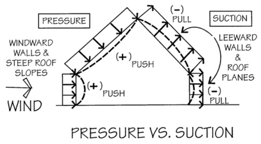
For uplift in EITHER roof system a collar tie (as opposed to a rafter tie) is used in the upper third connecting rafter to opposing rafter OR a metal strap from rafter to rafter is installed over the ridge, this ain't the hanger, it is another connection. In Marks drawing above when suction, or inflation from a blown out gable, pulls on the roof those upper collar ties or straps keep the roof from unzipping at the ridge.

In typical ridgeboard/ ceiling joist construction, the code heeljoint table specifies 16 commons and is lightly connected even then. The timbertoolbox calc came out of a class at VT. he connected sufficient to resist the rafter axial load, very conservative IMO, the tie tension is all that needs to be resisted if the rafter sits on a plate. If you tie as well as the calc that sucker could be connected out beyond the wall.

For the gothic buttress effect, intersecting wings will do the job.
 
Back
Top