• Welcome to the new and improved Building Code Forum. We appreciate you being here and hope that you are getting the information that you need concerning all codes of the building trades. This is a free forum to the public due to the generosity of the Sawhorses, Corporate Supporters and Supporters who have upgraded their accounts. If you would like to have improved access to the forum please upgrade to Sawhorse by first logging in then clicking here: Upgrades

More Cutting, Drilling and Notching

R802.7.1 also refers to another section of the code in Floors, R502.8.1, where the following figure shows the allowable notching of floor joists. Again, they use the D/4 limit. It doesn’t take an engineer to see that on the left side of this figure the notch will definitely weaken the joist. The deeper the notch, the greater the impact.

View attachment 10889

Actually... it's engineering specifically that says the D/4 notch at bearing is fine. A 2x10 notched down to the height of a 2x8 at bearing still gets all the credit as a 2x10 for the span and it makes perfect sense when looked through the lens of engineering.

The two stresses a spanning member experiences are shear and bending. Shear is greatest at bearing and bending is greatest in the middle of span. Bending stress is what creates deflection and is the first limiting factor to maximum span. Long before shear becomes too great at the bearing location, you have already exceeded deflection through bending.

This is why you cannot notch the middle third. Bending is resisted in the top and bottom of the joist and it's maximum at the center (middle third).

Shear on the other hand is greatest at the bearing location. For example, where a 2x10 is required for a span in order to stay within deflection, a 2x8 is plenty large enough to resist the shear at bearing from the load collected over that span.

The way the notching limits are presented for rafters will essentially ensure the heel is supported when using the minimum required bearing area of 1.5 inches for prescriptive designs. I agree that the information might not be presented in the easiest to understand manner, but the science is solid. Proposals for 2027 are due January 2025.

Here is an article of mine that explains the Science of Simple Spans that is the root of allowable notching: https://www.finehomebuilding.com/project-guides/framing/the-science-of-simple-spans

Here is a clip of mine explaining bending, shear and notching limits.
 
Would this be that?

2020 CRC:
R802.6 Bearing. The ends of each rafter or ceiling joist shall have not less than 11/2 inches of bearing on wood or metal and not less than 3 inches on masonry or concrete. The bearing on masonry or concrete shall be direct, or a sill plate of 2-inch minimum nominal thickness shall be provided under the rafter or ceiling joist. The sill plate shall provide a minimum nominal bearing area of 48 square inches.
Yeah...I guess if it is the "point" at the edge, not 1.5"
 
The way the notching limits are presented for rafters will essentially ensure the heel is supported when using the minimum required bearing area of 1.5 inches for prescriptive designs.
Do you mean presented in passing as part of Figure R802.7.1.1, when the text of R802.7.1 doesn't specify how to apply the end notch limits in R502.8.1 to rafters?

If so, that's pretty weak sauce in the IRC and should be clearer. I'm not clear at all that the implications of end notch measurement and limitation implied by figure R802.7.1.1 are supported by engineering. Nor is it particularly clear how to extrapolate from that one figure to a procedure for determining end notch depth for other rafter bearing possibilities.

Cheers, Wayne
 
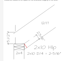
The notch depth is measured to the far side of the plate on rafters for some reason which is what all of this is about.........Your 2x10 hip image is not....

1687897583450.png
 
So, Glenn you agree that these two figures are equivalent and both are allowed:

View attachment 10892

I'm not going to give a simply answer to what is not at all a simple question.

1) All that is mandatory regarding this subject is provided in Chapter 3. All loads must be transferred to the earth.
2) How would a free citizen like to build this load transfer to ensure it will meet the requirement in chapter 3? That's up to them. There are untold numbers of methods. However, they have to have validation.
3) Chapter 8 of the IRC provides recipes (validation) for a few methods and materials. Those recipes are called prescriptive design. Like any recipe, the end product can only be expected if you follow the recipe. Otherwise you need a chef (design professional) to provide different, validated recipes or they can just modify a portion of the IRC recipes, as stated at the beginning of chapter 3.
4) The IRC recipes are written around basic, common, and normal meals. Like green bean casserole.
5) Notching a rafter the way you have show is not the way provided in the IRC recipe. Historically that goes way back in time. The birdsmouth cut is on the other side of the wall. The method you have shown is not the conventional method. (NO, this does not mean I would blindly ask for an engineer if I were the BO.)
6) So to answer your question. The detail on the left was not written into the recipe we currently have. That doesn't mean it's "not allowed" or "allowed" That means someone knowledgeable in wood engineering would need to evaluate it and ensure it meets the mandatory requirement in Chapter 3.

That is the IRC answer.

The stresses that occur in the wood and were used in creating these prescriptive design limitations are well explained in the video I posted previously.

The American Wood Council (formally AFPA) is the creator of the figure in chapter 8 that was part of a change for 2012. Prior to this the language of notching was the same as for joists. They made the figure to illustrate those limits based on conventional framing methods. That was their idea for how to present the information. They tend to know a lot about wood engineering. More than me, that's for sure. They are a huge source of my continued learning about wood engineering.

So as I said in my first post, the way the information is presented may not be what everyone likes. It may not show the recipes and recipe modifications some folks like and might absolutely work just fine. That's why everyone can propose changes or new recipes. That's also why the IRC is now over 1100 pages. I should probably stop here, but I have much more to say about this subject in general. It's not practical to have prescriptive design for every possible way to build. That's why professionals working in code need to have a full understanding that prescriptive design in the code is not the end all be all. It's one way. It doesn't say anything about other ways. The code makes that very clear in R104.11

I don't mean to sound like I have an attitude in the above text. Sorry if it comes across that way. I would be happy to take part in collaboration for a new way to present the information in a recipe that will allow for the most variation within the single method. Cheers!
 
Last edited:
The notch depth is measured to the far side of the plate on rafters for some reason which is what all of this is about
In that image, it is not at all clear what feature of the layout is the salient feature that should be extrapolated to other cases.

You can look at that image and say "the salient feature of the diagram is that the line defining the bottom of the notch hits the top exterior corner of the wall." But a perfectly reasonable alternative is to say "the salient feature of the diagram is that the cut rafter does have an edge parallel to the bottom edge of the full depth portion, and the distance between those two lines is the notch depth." Then without a rafter tail, there's no notch, and so no R802.7.1 problem.

To use Glenn's terminology, the recipe is not properly specified for determining rafter notch depth. The single diagram doesn't tell you how the bottom line of the notch was determined, just that some procedure was used and here's the result for this case.

Cheers, Wayne
 
Glenn, I appreciate your input and you video was excellent. However, (there's always a however) if we take figure 802.7.1.1 as the D/4 dimension for all rafters including hips and valleys, then every conventionally, stick-framed roof is against code since it is impossible to make the notch less than this D/4 dimension regardless of the pitch. Just saying. . .
 
Glenn, I appreciate your input and you video was excellent. However, (there's always a however) if we take figure 802.7.1.1 as the D/4 dimension for all rafters including hips and valleys, then every conventionally, stick-framed roof is against code since it is impossible to make the notch less than this D/4 dimension regardless of the pitch. Just saying. . .
Thank you. No "however" needed though. We completely agree that hip and valley rafter prescriptive design is basically non-existent. Even the AWC wood frame construction manual is woefully inadequate at providing clear guidance for hips and valleys. My newest class is a full day course "Conventional Wood Frame Construction". I am a former framer, so I have real world understanding of conventional framing (cut-in roofs). I also am a historian of construction and codes which is how we empirically established so much of the wood framing codes we still have today. I did a ton of research for this class and where my class falls short in teaching codes about framing is hips and valleys. I have a 1958 conventionally framed roof house and yes, my hip rafter cuts do not comply with this and have and continue to function just fine.

I am definitely not defending the IRC recipe for hip and valleys. I also think the IRC could better present the limitations.
 
I downloaded the article but I can't get it to load up here......still trying......gave up
 
Last edited:
R802.7 Cutting, drilling and notching.

In my area current economics have caused many builders to now opt for stick-framing over trusses. This section of the IRC has been discussed at length by this forum, yet no one has come up with a complete explanation of its apparent contradictions. There are two separate but related issues that have been discussed: 1) The depth of notch limit and 2) Toe support.

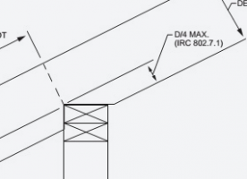
The diagram below makes no sense to me except for the part about the rafter cantilever. Why would the code limit the depth of the notch on a rafter to D/4 as measured in the figure below? I have seen rafters framed off of subfloors where the notch was nearly full depth. Jack rafters for overlays are full depth. If we ignore the tail, and the toe of the birdsmouth is solidly supported, what’s the problem?

View attachment 10890

Hip and Valley Rafters

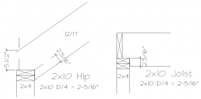
The reason I insist on beating this horse is that if one follows the code precisely using the smallest bearing allowed (1.5”) for rafters and then uses the next size up (2” nominal larger) as required for the hip, it is impossible (using standard techniques) to make the notch on the hip less than D/4 regardless of the pitch. See the figure below. Interestingly, it is also impossible to support the toe unless using 2x6 walls or using a 12/12 pitch for 2x4 walls.

One must assume the code is not banning the common practice of stick-framing. Are hip and valley rafters, therefore exempt? If one uses engineered material like an LSL or LVL, it is possible to engineer your way out of these issues, but with conventional lumber it is much more difficult. There are many videos online that describe techniques of fabricating hip and valley rafters. All seem to go out of their way to avoid discussing these issues while all appear to violate the D/4 limit as shown above.

View attachment 10887


If we read R802.7.1 carefully, it appears to refer to the overhang cantilever in figure R802.7.1.1 as an exception, “. . . except that cantilevered portions of rafters shall be permitted in accordance with Section R802.7.1.1.”

R802.7.1 also refers to another section of the code in Floors, R502.8.1, where the following figure shows the allowable notching of floor joists. Again, they use the D/4 limit. It doesn’t take an engineer to see that on the left side of this figure the notch will definitely weaken the joist. The deeper the notch, the greater the impact.

View attachment 10889

The general statement it makes regarding structural members is, “Notches at the end of the member shall not exceed one-fourth the depth of the member.” I would suggest that, as it pertains to rafters, this figure would be analogous to an unsupported toe of the rafter as shown below with the D/4 dimension changed to reflect the impact to the weakening of the rafter.

This is a figure comparing 2x10’s notched to the maximum depth of D/4. The figure on the right is code compliant. Is the figure on the left? Many would argue that neither are “proper” or at least ideal and should be avoided. The question is, is this what the ICC is attempting to say? The way we measure the depth of the notch should be related to its impact on the structural integrity of the rafter.

View attachment 10888
Please do not forget, the Residential code is strictly prescriptive. If it cannot be achieved by those parameters, then the Building Code and a licensed professional is to be used. You may not appreciate that, but that is the code publication.
 
Top