• Welcome to the new and improved Building Code Forum. We appreciate you being here and hope that you are getting the information that you need concerning all codes of the building trades. This is a free forum to the public due to the generosity of the Sawhorses, Corporate Supporters and Supporters who have upgraded their accounts. If you would like to have improved access to the forum please upgrade to Sawhorse by first logging in then clicking here: Upgrades

Stuck on Winder Layout

from '06 IRC:

Winder treads shall have a minimum tread depth of 10 inches (254 mm) measured as above at a point 12 inches (305 mm) from the side where the treads are narrower.Winder treads shall have a minimum tread depth of 6 inches (152 mm) at any point. Within any flight of stairs, the largest winder tread depth

at the 12 inch (305 mm) walk line shall not exceed the smallest by more than 3/8 inch (9.5 mm).
 
Tom, I would measure the 12 inches from the stair side edge of the center post, similar to circular stair measurement. If there is no post and just guard, I would actually measure to the very outside edge of the tread. I would not stop at the baluster.

My reasoning is that if there is no post it is more than likely very gentle winder and not a sharp 90.

DA BEARS!
 
TJ,

My prior post is directed at the latest 2009 walkline wording for the defined location. If you check out the commantary it is specific for using the widest point within the flight, not the shortest, hence my drawing.

The 06, though does not define location of walkline in a fixed term location, it leaves the door open and thus one need be creative and conclude that the walkline is just 12" in from edge.

Lynn, you are correct about the 6" on the outer side, that is normally fixed with just doing a 45 degree turn out 6" from the wall, I did not draw that in my sketch, figuring it was a given, but I guess I should be more detailed. This turn out also takes care of the wall post for termination of the guard.

The point I was getting at is by doing more than 2 interlocking winder treads, and meeting the 6" min edge depth, you will end up eating up more travel distance than adding in a landing, unless you are doing a descending 180 degree wrap, but then you would still extend out further than a landing turn on a 90 degree layout vrs the 180 return for full descending.
 
In the last jurisdiction I worked for, there was a builder that built this same style of "winder" (where the stairs were mostly straight, and a winder was incorporated into the middle, identical to the 1st drawing from DRP). The BO had alot of heart burn over it. Finally the builder came up with (paid for) an official interp from ICC (based on either '03, or '06 IRC) where they stated with regard to the walk line and the 3/8" difference in the tread depth, that the measurement for the 3/8" max variation only applied to the winder portion of the stairs. Basically, the tread depth for the straight portion was approved at 10" min (or what have you), then the tread depth for the winding portion only had to be consistent within itself (12" or 14" or whatever, varying max 3/8"). Then the rest of the parallel treads had to go back to the original 10".

At the time it seemed awfully strange, but based on that interp, we let them proceed. It was almost as if there were two different flights of stairs without being broken up by landings.

I still don't agree with it, but that's what we approved based on the interp. I don't know how to find such interps from ICC. There may be a way to find it. However, it may not work with the '09, but it is out there, somewhere.
 
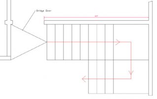
Glennman, yes, I saw a clarification of that during my reading of 311.7.4.2 of the '09. "Consistently shaped winders at the walkline shall be allowed within the same flight of stairs as rectangular treads and do not have to be within 3/8" of the rectangular tread depth." That has been my understanding of the intent, and I do agree with it. Don't misunderstand my sentiments... despite all my oscillations I'm not a winder fan.Tom, thanks for bearing with me and clearing up some of the terminology and measurement points. I've attached a plan view, it is 9'5" to the bath door but I'd like to keep the overall run in that direction to 9'3 max. The finish floor total rise is 108". The entry is fairly close @ 6'5". The lower run is also 38-1/2" wide which should pass min clear width between the newels. The constraint is the clients' desire to make the lower run into the floor as short as possible in the entry area. So yes, if the winder on the landing is as short as it can get, that is the solution. They were pushing for it being more compact and asked if we couldn't put another winder on the landing and buy more room. That was my next round of sketches, exploring if that could work. That side journey also exposed a real weakness in my understanding so I'm also trying to fill that gap. I gather that after a single winder on the landing I'm growing as compared to minimal rectangular 9" treads stepping off the landing?Thanks again,Don P

View attachment 213

View attachment 213

/monthly_2010_09/baldwinstairSept28b.jpg.ab3e3ab86bbeb8796ef59008ec616463.jpg
 
Last edited by a moderator:
I'll make this another post so it'll be easier to say "disregard your last post, thinking problem".Let me see if I understand some concepts. I drew the baluster line 1" inside the newels on both flights. I then drew a line inside that 12", from both the upper and lower flights. I then swung a 12" arc that is tangent to both 12" lines. I added another winder. I swung a 6" arcfrom the corner of the newel to make sure I had 6" at any point on the tread below it. I measured and balanced the length of chords across the arc and down the lowermost winder (Is this the correct way to measure that?). I also nipped the corner of Lynn's tread (That actually looks like its more likely to cause trouble to me?)If that all worked it did save almost 4 more inches.

View attachment 214

View attachment 214

/monthly_2010_09/572953b999a34_baldwinstairsbSept28.jpg.177be2f627c0d9a9e41e971dd7f09a3b.jpg
 
It does not appear that 2009 fixed anything. It just codifies inconsistancy. Great.
 
DRP,

You have met the techinal portion of the code, however, it is really not that good of a stair layout for functionality.

You noted that the doorway was a bathroom, so this might not work, but what if you shifted the stairs to the right and put a double descending platform with a 180 degree turn, and shifted the door to be under the staircase rather than at the base?

I don't have the whole floor plan, nor know were in the construction phase you are, but, this seems awfuly tight fit and the stairs are being shoe horned in place.

You also might want to think of changing the guard and handrails from wood to metal, this would save you on post width and clear width concerns by about 3 - 4 inches.

The following layout would be a better walking surface

acgrevised.jpg
ACGRevised.jpg

My skecth mostlikely involves a lot of fixture moving at this point, so it is mute, but just what I would see to solve the tight turn.
 
Last edited by a moderator:
Thanks for the considerable time and patience here Tom,

Mostly I'm glad to have finally wrapped my head around the technical aspects. There is actually a bathroom behind that door but there is a closet behind the doorway you've drawn. Your design can work in the original location, that sketch was shot down as well. I'm in the position of presenting the options and explaining the virtues and drawbacks of each. In the end I will build a compliant stair of their choosing. The bright spot is that I know the designs offered are code compliant, the original design was not.

TJ, Another way of thinking about it. The winder is a slice of pie. We have decided that it can be no narrower than 6" and by the time it is 12" wide it needs to be at least 10" wide. Making it the same as the rectangular treads at 12" might seem consistent in some way but at any other point it will be something other. It would also make it pretty much unbuildable, you would have locked 2 points of a triangle. I think that would essentially define a triangle. It will never really be a tread consistent with the others, these constraints simply make it relatively safe in the normal travel path. I can see and agree with the intent there.

I really do appreciate everyone's input.
 
Hear is the best reference for interpretation of stair layouts

rather than being the "Mother of Invention"

Ask Mom or in this case SMA

Stair Manufacturers association.

http://www.stairways.org/pdf/2006%20Stair%20IRC%20SCREEN.pdf

This orginization will provide state specific Code Specific document for any state

They did one for us in RI because we know best and change the national standards.

If you can't find the solution at this site you are trying really hard to avoid compliance
 
I started there, this situation wasn't really covered in the Stairways pdf, but yes that is an excellent link. I refer to it often and pass it around.Another way to look at google sketchup. It is a free download, several forums allow posting the skp file directly. Instead of posting screenshots and others having to ask for particulars, I could have posted the file, it could have been the entire 3d house model. That makes collaboration pretty easy. I've attached an example that I had on the computer of a drawing I worked up for an ag building. I've been pretty impressed with what it can do.

View attachment 217

View attachment 218
 
Last edited by a moderator:
When I first read this topic I thought the discussion was going to be on the placement of winders....you know those thangs that you open up to let the fresh air in.
 
Top