• Welcome to the new and improved Building Code Forum. We appreciate you being here and hope that you are getting the information that you need concerning all codes of the building trades. This is a free forum to the public due to the generosity of the Sawhorses, Corporate Supporters and Supporters who have upgraded their accounts. If you would like to have improved access to the forum please upgrade to Sawhorse by first logging in then clicking here: Upgrades

Unresponsive Inspector

Okay, to clarify, you won't need a "header beam" just a simple "header" plate which would by a flat 2x4 or 2x6 (match with the rest of the wall stud framing.... 2x4 for 2x4 wall and 2x6 for 2x6 wall. A poster did make a post with the pertinent code section and language. However, there can be exceptions for design/engineering principles. You wouldn't need to use a 2 to 3 ply 2x (8, 10, or 12) beam and sheet(s) of plywood to bring it to flush with the wall studs on non-bearing walls and where windows or door is not in the shear resistance areas of the wall paneling. The wall should be adequately designed for shear resistance as required by code and should be when it is prudent.
Rick, you are on fire this morning. I am thrilled to see all of your well-thought-out posts. Have a great day.
 
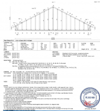
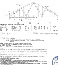
I would be cautious saying a gable truss isn't bearing. I just checked a few and found that most were, though not much. The only way to say for sure is to see the design drawing. In the the ones I just looked at there would be about 500 to 750lbs over a typical size window. This would be distributed somewhat by the plates and sheathing, but they definitely do "bear" in the location. This is a very light load, and the as far as I can tell the prescriptive tables do not account for the load in that plane, but it is something to watch out for. Here is one such gable truss I found in my files. Clearly non-bearing on one side, clearly bearing on the other. In the field, without this drawing, it could be mistaken for a non-bearing location.

1632164538101.png
 
The definition determines if it is a load bearing wall

[BS] WALL, LOAD-BEARING. Any wall meeting either of the following classifications:

1. Any metal or wood stud wall that supports more than 100 pounds per linear foot (1459 N/m) of vertical load in addition to its own weight.

2. Any masonry or concrete wall that supports more than 200 pounds per linear foot (2919 N/m) of vertical load in addition to its own weight.
 
The ends of the gable truss would be bearing but trusses are generally design to free-span without intermediate supports. Otherwise, it is not a proper truss when we are talking about "truss" roofs. The gable end exterior walls don't normally require header BEAMS (just a simple flat 2x4 or 2x6 header around the window opening. This is because the roof loads on the truss runs across the top chord to the bottom left and right. The bottom chord functions much like a rafter tie. This bottom chord is not structurally resting on intermediate walls unless it is a really big roof and you then are doing something like you would with truss joists. On a residential home, the roofs just aren't likely to have that large of a span. The gable end wall (exterior wall) would be transferring its loads to those two corners which WOULD be where you would bearing walls or a row of pilasters or moment frame ( Post-Beam frame) going perpendicular to the direction of the truss span to support each of the roof trusses above. Trusses are engineered systems and engineering principle is for trusses to span from end to end without requiring intermediate or continuous support. Otherwise, your entire gable-end wall from the bottom chord of the truss to the ground would be your bottom chord.

Generally, in residential buildings, you don't have a truss at the gable end wall. You would have a simple gable pointed stud frame wall and rafters going up to and ultimately supporting the very ends of the purlins. The trusses would be intermediate in between the gable-ended stud frame walls & simple gable-end rafters to support the end of the purlins. If you are dealing with an unusually high load. You might need to incorporate a horizontal member in the stud framing that is connected to the rafters (which may be a 4x6 or 6x6 or something like that) and function as a lateral tie However, once, you are pretty much below those truss bottom chords / ceiling joists, etc., the gable end wall would generally be non-bearing and often would not carry loads other than shear/lateral resistance design matters. Of course, you have to assess the design as a whole with the complete set of plans. Having said that, and agree with that, it would be unlikely that the gable end walls being load-bearing. The very engineering principle of gable is to transfer the loads to the side walls.

A simple example, my house. It's Victorian that is roughly 23 ft wide x 50 ft long. The long axis is north/south. The gable ended walls are the north and south stud framed walls. The load bearing walls bearing the roof is the walls that forms the east and west elevation. The center wall line supports the floors at mid-point. In a gable truss roof, the truss would span the whole 23 ft. It would be these east and west walls that would support the roof. Now, my house actually is rafter roof system with a rafter tie. The rafters goes spans the 23 ft. The north and south exterior roofs are not considered "load-bearing". Yes, it technically supports some load like basic dead load and so forth but the loads are directly transferred to foundation through studs. Being balloon-framed, it literally continuous to sill plate/beam on top of the foundation wall. Otherwise, the rafters would carry the load. A proper truss would span all the way across and needs no interior load bearing walls to support the truss at any intermediate point other than the bottom left and right corners of the basic roof truss overall triangle. A roof truss is basically a triangle shaped roof or (in some cases other shaped roofs like a barrel vault or dome) made of components forming smaller triangles that ultimately forms the overall roof form. The basic gable roof is that forms an "A" shape where the rafter tie is the bottom chord of the simple truss element in the "A" shaped form. Sometimes, the ceiling joists doubles as a rafter tie and therefore is a simple truss made of rafters and ceiling joists. With a relatively standard engineered truss, they would span 25-40 ft. depending on how you engineer the truss whether that be a truss for typical residential roof spans or if you are dealing with a multi-ply wooden truss or modern steel roof trusses designed for larger tributary load capacity. In any case, they typically span long distances by design otherwise, what's the point in using trusses instead of conventional rafter framing.

The gable end wall is just part of enclosing the building but is not necessarily there to support the roof live load, dead, load, wind load, etc. I did mention earlier where the gable end wall may serve as part of the shear/lateral resistance system. That would a case where header beams would be used but then it's part of an overall lateral force resisting system. Generally, they are not "load bearing walls". SDS, you are right that you have to see the design drawings.

However, in your truss example, the load bearing point in truss is moved further in instead of at the very end corner. You can do that with the truss design. Therefore you need to support the roof with a load-bearing system but you don't need to continuously support the bottom chord of a truss. The wall that parallels but under the truss chords needs not be "load-bearing" unless it's part of a shear resistance system. In your example, that right hand area where the hash pattern could have been required by design for lateral force resisting system (bearing wall with shear wall paneling, etc.) in some buildings/homes. In which case, you would have a header beam if you have any windows in that area below the truss. Generally, as in normal rule of thumb, the gable ended wall would not be "load bearing" because the roof loads are transferred to the end points where rafter or truss are seated on the walls at the end or near the end. In my example of the 23x50 foot house using a truss roof would be the east and west walls. The north and south walls would not usually be load bearing. They would not be taking the roof load because the load by force of gravity would be transferring primarily to the end. The studs would just kind of mitigate deflection issues because they do technically absorb dead load but are not absolutely necessary to be double-top plated because even a single-top plate would suffice with the partial load from only a partial tributary area. If you get really scientific about it, "non-load bearing" walls are not "zero-load bearing wall".
 
The definition determines if it is a load bearing wall

[BS] WALL, LOAD-BEARING. Any wall meeting either of the following classifications:

1. Any metal or wood stud wall that supports more than 100 pounds per linear foot (1459 N/m) of vertical load in addition to its own weight.

2. Any masonry or concrete wall that supports more than 200 pounds per linear foot (2919 N/m) of vertical load in addition to its own weight.

Any wall intended to support weight is loadbearing walls. Non-load bearing walls are not zero-load bearing wall. It supports itself and will incidentally support some load that by a structural design reason, if non-load bearing walls were removed, the structural systems would not collapse. They may help the overall structural system. This would be contingent on the buildings being adequately and properly designed/engineer. With old buildings from way before building codes, there can be all kinds of crazy situations where a wall the is "non-loadbearing" by how its framed is in fact carrying load that if removed would result in some part possibly collapsing because it was idiotically designed/built.
 
Ignorance is empowering.

The prescriptive code provisions are applicable in certain limited conditions. When these conditions do not exist you need to deal with the non-prescriptive code provisions which inevitably requires consulting with a registered engineer or architect.
 
1632195403794.png
This typical drop top chord gable end truss typically what we see around here. 36' to 40' spans are common and a 45psf roof snow load and 115 mph ultimate wind speed exposure "C".
Question If this truss Has a 2 ft tributary load on each side and all of the supports for the top are vertical how is that not transferring the top chord loads evenly to the bottom chord and thus to the wall? Is it less than 100 lbs per linear foot and therefore of no concern?
 
Most of the verticals in the gable truss drawings I looked at considered a load of less than 250lbs at each vertical. I think this is probably a calculation based on the overhand designed into the truss and the tributary load from 1/2 of the truss spacing. IMHO, these trusses are bearing. Does that mean that prescriptively we are going to require a built up header? Typically not for me. And even if I wanted to, there doesn't appear to be a table for trusses bearing parallel to the building width. (Never really liked these tables, but they are what we have). In the OP, it sounds like the inspector and/or the boss didn't have a clear understanding of this, and then everyone dug their heels in. If there are truss design drawings I think the issue could be resolved rather quickly...if personal feelings and opinions can be put aside. My comment was based on the contention that they are typically non-bearing. Some trusses require continuous bearing ( for various reasons as others have noted), some have concentrated loads.

In the 1st drawing, the hatched bottom chord indicates a requirement for continuous bottom chord bearing, which is verified by note 7.
In the second drawing, even thought the truss looks to be symmetrical, one side is clearly non-bearing, but the other is bearing. And, in fact, joint 12 has considerably more reaction than the similar joint 9, which has no bearing requirement.

I am not an engineer so maybe my understanding of these drawings is wrong. When I inspected I required the layouts and shops on site. Even though I typically considered a standard gable truss as "non-bearing", I would look for the hatch, and if I saw it I would consider why.
1632251004053.png
1632251038045.png
 
View attachment 8243
This typical drop top chord gable end truss typically what we see around here. 36' to 40' spans are common and a 45psf roof snow load and 115 mph ultimate wind speed exposure "C".
Question If this truss Has a 2 ft tributary load on each side and all of the supports for the top are vertical how is that not transferring the top chord loads evenly to the bottom chord and thus to the wall? Is it less than 100 lbs per linear foot and therefore of no concern?

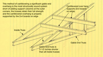
The truss is just the trusses. It is not the wall. The picture doesn't show the wall itself. Typically, the load bearing walls would be running in the same direction as those cantilevered overhang supports and at a point likely where the gable end truss top chord joins the bottom chord. No wall or any bearing wall would not necessarily be needed running in-line (parallel) with the bottom chord. The bottom chord of a truss does not typically required to have intermediate walls or other supports under it other than at or near the end points. You're trusses may overhang and the load bearing wall in maybe about 18" to 36" or so in-set from the very end of the trusses at bottom left & right corner. Any wall under the truss except those running perpendicular to the direction of truss span (end to end), normally, does not require load-bearing walls or any wall. Those walls, posts&beam systems, etc. are more for moisture envelope and subdividing the interior spaces into rooms or defining function areas. Those vertical studs are not normally requiring to transfer through to ground. You may, if you want to. You can have a wall under it with double-top plates.
 
Most of the verticals in the gable truss drawings I looked at considered a load of less than 250lbs at each vertical. I think this is probably a calculation based on the overhand designed into the truss and the tributary load from 1/2 of the truss spacing. IMHO, these trusses are bearing. Does that mean that prescriptively we are going to require a built up header? Typically not for me. And even if I wanted to, there doesn't appear to be a table for trusses bearing parallel to the building width. (Never really liked these tables, but they are what we have). In the OP, it sounds like the inspector and/or the boss didn't have a clear understanding of this, and then everyone dug their heels in. If there are truss design drawings I think the issue could be resolved rather quickly...if personal feelings and opinions can be put aside. My comment was based on the contention that they are typically non-bearing. Some trusses require continuous bearing ( for various reasons as others have noted), some have concentrated loads.

In the 1st drawing, the hatched bottom chord indicates a requirement for continuous bottom chord bearing, which is verified by note 7.
In the second drawing, even thought the truss looks to be symmetrical, one side is clearly non-bearing, but the other is bearing. And, in fact, joint 12 has considerably more reaction than the similar joint 9, which has no bearing requirement.

I am not an engineer so maybe my understanding of these drawings is wrong. When I inspected I required the layouts and shops on site. Even though I typically considered a standard gable truss as "non-bearing", I would look for the hatch, and if I saw it I would consider why.
View attachment 8245
View attachment 8246

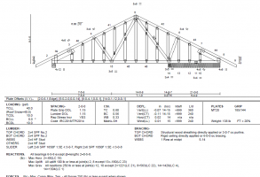
It's stamped by an engineer. Consult the engineer and do accordingly. Any window or door under the 'hatched' "continuous bearing support" should have header beams over the window. The areas that do not have a continuous bearing support requirement, does not necessarily require header beams over the window. If any portion of a door or window is under that continuous load bearing area, you should have a header beam continuous over the window and door. Like I said, consult the engineer that stamped the drawings.
 
It's stamped by an engineer. Consult the engineer and do accordingly. Any window or door under the 'hatched' "continuous bearing support" should have header beams over the window. The areas that do not have a continuous bearing support requirement, does not necessarily require header beams over the window. If any portion of a door or window is under that continuous load bearing area, you should have a header beam continuous over the window and door. Like I said, consult the engineer that stamped the drawings.

Usually walls in-line under the truss's bottom chord is not required to be load-bearing. This is because trusses do not usually require continuous load-bearing support running in-line with the truss. Typical roof trusses are bearing load on each end within 5-ft. from the end of the trusses on each side and those run perpendicular to the direction of truss span so the continuous bearing wall supports each truss on that end. Maybe I'll have to sketch something to illustrate.
 
Comment from the peanut gallery...I would physically go in to the permit/inspection counter if at all possible. You never know what's going on. Was the inspection accidentally passed in the computer system? Has the BO been sick? Is there a director who you can contact? I agree with working up the chain of command. I would first do your due diligence, which means doing a little more than just leaving voice mails. Personal experience....it can take up to 4-5 days to get through voice mails.
If not - default to classic T's tag lines... ;)
 
I agree that there is a slight "load" involved. To be clear, I am not the one calling it a nonbearing wall, it is the IRC.
If the 2x6 rafter can support the roof over an 8' span, then why can't it support it over a 3' span? We are not really talking about supporting roof load here. It is simply the intervening material between the rafter and the top of the window, i.e., osb, siding, drywall, insulation.
So you have waited ten days. Wouldn't it have been faster to just put in a double 2 x 6/2 x 8 header and be done and progressing? A true truss above the wall would make it non-loadbearing. Not what you got. You indicated that you agreed that it is slightly load bearing, with that admission you just lost the debate.
 
Curious as to how/if this was resolved.

My 2 cents as an architect:
1. If the inspector has a problem with what they are seeing in the field, he should provide a code citation. If not, they should let it pass.
[....]

I've had superintendents call me in a panic saying the inspector has a problem. I tell the superintendent to make me the bad guy, and tell the inspector I want him to write it up, including the applicable code reference. 30% of the time, the problem goes away right then. 60% of the time, a clarification call or email from me will lay the issue to rest. 10% of the time, the inspector was right, and I'm glad he found the issue and brought it to our attention.
When I find issues in field inspections, or, alternately, if I find issues during a plans review, I will *always* provide reference to the appropriate section of the Code or standard.
That does three things
1) provides the contractor/customer/designer some confidence that I didn't just pull something out of my yin-yang
2) Gives folks a chance to question my interpretation by checking the code themselves
3) Forces me, in odd situations, to actually verify that I am doing what I think I am doing, that I am in the right section of Code for the right building.

Reports on field inspections are to be written onsite, and provided before the inspector leaves...with the logical exception of "this is dang complex, I am going to have to delve into an obscure NFPA standard" situations.
Lintel over an opening in an exterior wall - that doesn't count as an exception in my book.
 
Top